Toyota RAV4 (XA40) 2013-2018 Service Manual: Inspection
- Inspect starter assembly
Notice:
These tests must be performed within 3 to 5 seconds to avoid burning out the coil.
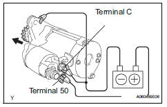
- Perform the pull-in test.
- Disconnect the lead wire from terminal c.
- Connect the battery to the magnetic switch as
shown in the illustration. Check that the clutch
pinion gear extends.
If the clutch pinion gear does not move, replace the magnetic switch.
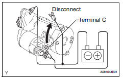
- Perform the hold-in test.
- Maintain the battery connections of the pull-in
test above, but disconnect the negative (-) lead
from terminal c. Check that the pinion gear
remains extended.
If the clutch pinion gear returns inward, replace the magnetic switch.
- Check the clutch pinion gear return.
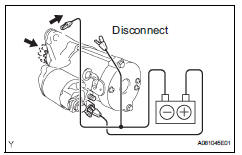
- Disconnect the negative (-) lead from the
switch body. Check that the clutch pinion gear
returns.
If the clutch pinion gear does not return, replace the magnetic switch.
- Perform the no-load performance test.
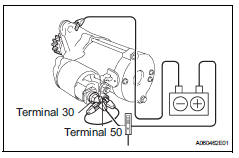
- Connect the lead wire to terminal c. Make sure that the lead is not grounded.
- Clamp the starter in a vise.
- Connect the battery and an ammeter to the starter as shown in the illustration.
- Check that the starter rotates smoothly and
steadily while the pinion gear is moving out.
Then measure the current.
Standard current: 90 a or less at 11.5 V
If result is not as specified, replace the starter assembly.
- Inspect magnetic switch assembly
- Check the plunger.
- Push in the plunger and check that it returns
quickly to its original position.
If necessary, replace the magnetic switch assembly.
- Check if the pull-in coil has an open circuit.
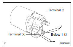
- Measure the resistance between terminals 50 and c.
Standard resistance:
below 1 
If the result is not as specified, replace the magnetic switch assembly.
- Check if the hold-in coil has an open circuit.
- Measure the resistance between terminal 50 and the switch body.
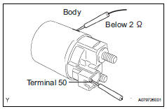
Standard resistance:
below 2 
If the result is not as specified, replace the magnetic switch assembly.
- Inspect starter armature assembly
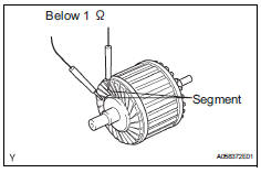
- Check if the commutator has an open circuit.
- Measure the resistance between the segments of the commutator.
Standard resistance:
below 1 
If the result is not as specified, replace the armature assembly.
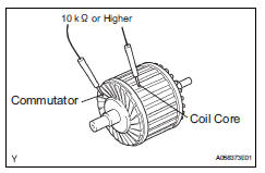
- Check if the commutator is grounded.
- Measure the resistance between the commutator and armature coil core.
Standard resistance:
10 k or higher
If the result is not as specified, replace the armature assembly
- Check the commutator for contamination and burns
on its surface.
If the surface is dirty or burnt, correct it with sandpaper (no. 400) Or a lathe
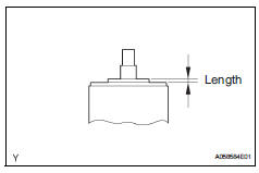
- Using a vernier caliper, measure the commutator's length.
Standard length: 3.1 To 3.8 Mm (0.122 To 0.150 In.)
If the length is greater than the maximum, replace the starter armature assembly.
- Inspect starter commutator end frame assembly
- Using a vernier caliper, measure the brush length.
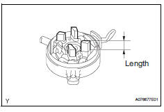
Standard length: 4.0 To 9.0 Mm (0.158 To 0.359 In.)
If the length is less than the minimum, replace the end frame assembly.
- Check the brush insulation.
- Measure the resistance between the positive (+) and negative (-) brush.
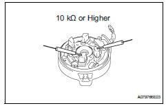
Standard resistance:
10 k or higher
If the result is not as specified, repair or replace the end frame assembly.
- Inspect starter clutch
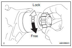
- Check the starter clutch.
- Rotate the clutch pinion gear counterclockwise
and check that it turns freely. Try to rotate the
clutch pinion gear clockwise and check that it
locks.
If necessary, replace the starter drive housing assembly.
 Disassembly
Remove magnetic switch assembly
Remove the nut and disconnect the lead wire from
the magnetic switch.
Remove the 2 screws holding the magnetic switch
to the starter drive housin ...
 Reassembly
Hint:
Use high-temperature grease to lubricate the bearings,
gears, return spring and steel ball when assembling the
starter.
Install planetary gear
Apply grease to the planetary gears an ...
Other materials:
Air conditioning amplifier communication stop mode
Description
Wiring diagram
Inspection procedure
Notice:
Turn the ignition switch off before measuring the resistances
of the main wire and the branch
wire.
After the ignition switch is turned off, check that the key
reminder warning system and light
reminder warning sy ...
Installation
Hint:
Use the same procedures for the rh side and lh side.
The procedures listed below are for the lh side.
When replacing the clip, heat the clip and body using a
heat light.
Standard heating temperature
Notice:
Do not heat the clip and vehicle body excessively.
Replace roof dri ...
Ecm communication stop mode (2005/11-2006/01)
Description
Wiring diagram
Inspection procedure
Notice:
Turn the ignition switch off before measuring the resistances of the
main wire and the branch
wire.
After the ignition switch is turned off, check that the key reminder
warning system and light
reminder warning system ...
