
Toyota RAV4 (XA40) 2013-2018 Service Manual: Starter
Components
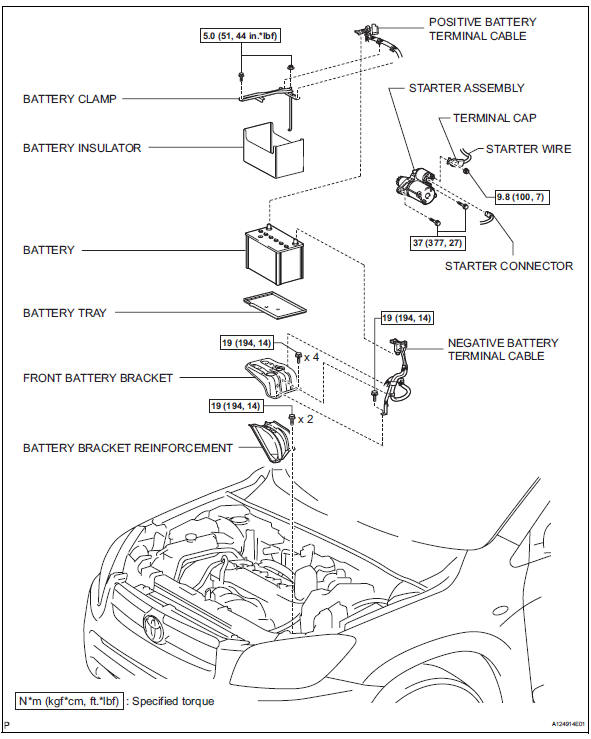
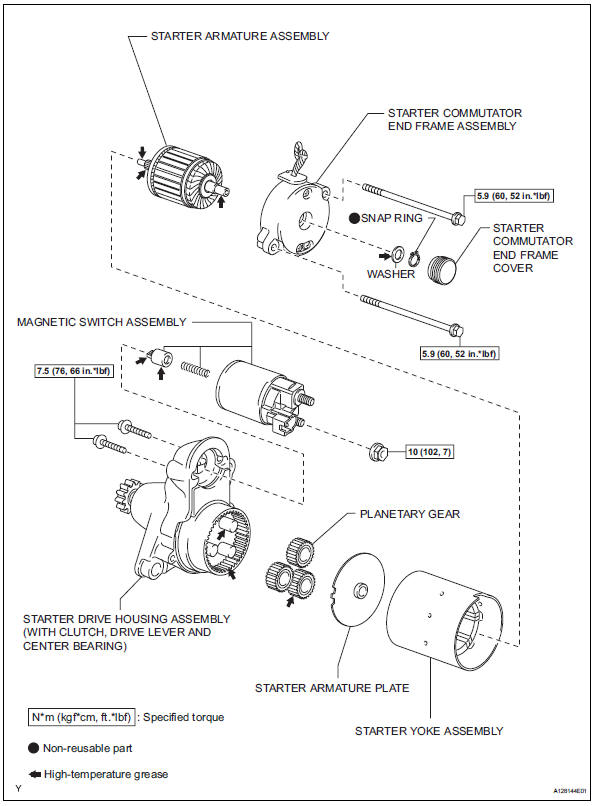
 Starting system
Parts location
System diagram
The starting system rotates the starter motor according to the
signals from the ignition switch and pnp switch.
...
 Removal
Disconnect cable from negative battery
terminal
Caution:
Wait at least 90 seconds after disconnecting the
cable from the negative (-) battery terminal to
prevent airbag and seat belt preten ...
Other materials:
Emission control system
Parts location
System diagram
On-vehicle inspection
Check fuel cut rpm
Increase the engine speed to at least 3,500 rpm.
Use a sound scope to check for injector operating
noise.
Check that the operating sounds stop momentarily
and then resume when the t ...
RSA (Road Sign Assist)
The RSA system recognizes
specific road signs using
the front camera to provide
information to the driver via
the display.
If the system judges that the
vehicle is being driven over
the speed limit, performing
prohibited actions, etc.
according to the recognized
road signs, it notifies
the driver ...
Air inlet damper control servo motor circuit
Description
The damper servo (air inlet control) sends pulse signals to indicate the
damper position to the air
conditioning amplifier. The air conditioning amplifier activates the motor
(normal or reverse) based on
these signals to move the air inlet control damper to the appropriate pos ...
