Toyota RAV4 (XA40) 2013-2018 Service Manual: Disassembly
- Remove magnetic switch assembly
- Remove the nut and disconnect the lead wire from the magnetic switch.
- Remove the 2 screws holding the magnetic switch to the starter drive housing.
- Remove the magnetic switch.
- Remove the return spring and plunger from the starter drive housing.
- Remove starter yoke assembly
- Remove the 2 through-bolts, and pull out the starter yoke together with the commutator end frame.
- Remove the starter yoke from the commutator end frame.
- Remove starter armature plate
- Remove the armature plate from the starter yoke.
- Remove starter commutator end frame cover
- Using a screwdriver, pry out the commutator end frame cover.
- Remove starter armature assembly
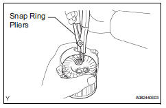
- Using snap ring pliers, remove the snap ring and plate washer.
- Remove the armature from the commutator end frame.
- Remove planetary gear
- Remove the 3 planetary gears from the starter drive housing.
 Removal
Disconnect cable from negative battery
terminal
Caution:
Wait at least 90 seconds after disconnecting the
cable from the negative (-) battery terminal to
prevent airbag and seat belt preten ...
 Inspection
Inspect starter assembly
Notice:
These tests must be performed within 3 to 5 seconds
to avoid burning out the coil.
Perform the pull-in test.
Disconnect the lead wire from terminal c ...
Other materials:
Using an anchor bracket
(for top tether strap)
â– Anchor brackets (for top
tether strap)
Anchor brackets are provided
for each rear seat.
Use anchor brackets when fixing
the top tether strap.
Outboard rear seats
Anchor brackets
Top tether strap
Center rear seat
Anchor bracket
Top tether strap
â– Fixing the top tether strap
to the an ...
Removal
(2006/01- )
Remove front wheel
Drain automatic transaxle fluid
Drain the automatic transaxle fluid for u140f (see
page ax-147).
Drain the automatic transaxle fluid for u241e (see
page ax-146).
Drain the automatic transaxle fluid for u151e (see
page ax-172).
Remove front axle hub nut ( ...
Terminals of ecu
Center airbag sensor assembly (w/ curtain
shield airbag)
Center airbag sensor assembly (w/o curtain
shield airbag)
...
