Toyota RAV4 (XA40) 2013-2018 Service Manual: Installation
Hint:
- Use the same procedures for the lh side and rh side.
- The procedures listed below are for the lh side.
- A bolt without a torque specification is shown in the standard bolt chart (see page ss-2).
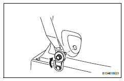
- Install rear no. 1 Seat outer belt assembly lh
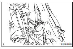
- Align the claws with the seat belt positioning holes, and install the retractor of the seat belt with the 2 bolts as shown in the illustration.
Torque: 8.5 N*m (87 kgf*cm, 75 in.*Lbf) for upper bolt
42 N*m (428 kgf*cm, 31 ft.*Lbf) for lower bolt
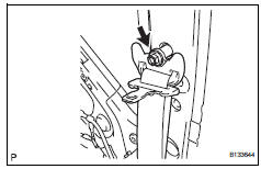
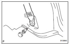
- Connect the shoulder anchor with the bolt.
Torque: 42 n*m (428 kgf*cm, 31 ft.*Lbf)
- Install inner roof side garnish assembly lh (w/ rear no. 2 Seat) (see page ir-52)
- Install rear no. 2 Seat outer belt assembly lh (w/ rear no. 2 Seat)
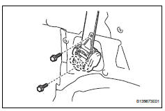
- Align the claws with the seat belt positioning holes and install the retractor of the seat belt with the 2 bolts as shown in the illustration.
Torque: 8.5 N*m (87 kgf*cm, 75 in.*Lbf) for upper bolt
42 N*m (428 kgf*cm, 31 ft.*Lbf) for lower bolt
- Connect the shoulder anchor with the bolt.
Torque: 42 n*m (428 kgf*cm, 31 ft.*Lbf)
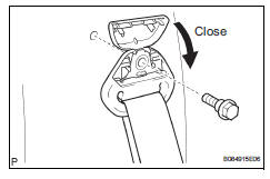
- Close the cover cap.
- Install inner roof side garnish assembly lh (w/o rear no. 2 Seat) (see page ir-51)
- Install deck trim side panel assembly lh (w/ rear no. 2 Seat) (see page ir-53)
- Install deck trim side panel assembly lh (w/ o rear no. 2 Seat) (see page ir-52)
- Connect rear no. 2 Seat outer belt assembly lh (w/ rear no. 2 Seat)
- Connect the seat belt's floor anchor with the bolt.
Torque: 42 n*m (428 kgf*cm, 31 ft.*Lbf)
- Close the cover.
- Connect rear no. 1 Seat outer belt assembly lh
- Connect the seat belt's floor anchor with the bolt.
Torque: 42 n*m (428 kgf*cm, 31 ft.*Lbf)
- Attach the lap belt outer anchor cover.
- Install reclining remote control lever bezel lh (w/o rear no. 2 Seat)
- Install rear floor finish plate (see page ir- 55)
- Install rear no. 1 Floor mat support side plate (see page ir-55)
- Install rear floor no. 3 Board
- Install rear floor no. 2 Board
- Install rear no. 2 Seat assembly lh (w/ rear no. 2 Seat) (see page se-121)
- Install rear no. 2 Seat assembly rh (w/ rear no. 2 Seat) (see page ir-55)
- Install no. 2 Seat leg cover lh (w/ rear no. 2 Seat) (see page se-123)
- Install no. 2 Seat leg cover rh (w/ rear no. 2 Seat) (see page ir-56)
- Install no. 2 Seat hinge cover lh (w/ rear no.
2 Seat) (see page se-123)
- Remove no. 2 Seat hinge cover rh (w/ rear no.
2 Seat) (see page ir-56)
- Install deck board assembly (w/o rear no. 2 Seat)
- Install rear floor no. 1 Board (w/o rear no.
2 Seat)
- Install tonneau cover assembly (w/o rear no. 2 Seat)
- Install package tray trim pocket subassembly (w/o rear no. 2 Seat)
- Install rear door opening trim weatherstrip lh
- Install rear door scuff plate lh (see page ir-57)
- Connect cable to negative battery terminal
 Removal
Hint:
Use the same procedures for the rh side and lh side.
The procedures listed below are for the lh side.
Disconnect cable from negative battery
terminal
Caution:
Wait at least 90 ...
 Rear center seat outer belt assembly
Components
Removal
Caution:
Wait at least 90 seconds after disconnecting the cable
from the negative (-) battery terminal to prevent airbag
and seat be ...
Other materials:
Brake system malfunction
Description
This dtc is output when the vsc system has a problem. Check the vsc system
when this dtc is
output.
Inspection procedure
Hint:
This circuit uses can communication. Therefore, if there are any malfunctions
in the communication
circuit, one or more dtcs in the can communi ...
Removal
Hint:
Use the same procedures for the rh side and lh side.
The procedures listed below are for the lh side.
Disconnect cable from negative battery
terminal
Caution:
Wait at least 90 seconds after disconnecting the
cable from the negative (-) battery terminal to
prevent airbag and ...
Child restraint systems
Before installing a child
restraint system in the vehicle,
there are precautions
that need to be observed,
different types of child
restraint systems, as well as
installation methods, etc.,
written in this manual.
Use a child restraint system
when riding with a small child
that cannot properly use a ...
