Toyota RAV4 (XA40) 2013-2018 Service Manual: Installation
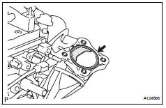
- Install throttle body
- Install a new gasket onto the intake manifold.
- Install the throttle body and fuel pipe clamp with the 4 bolts.
Torque: 30 n*m (305 kgf*cm, 22 ft.*Lbf)
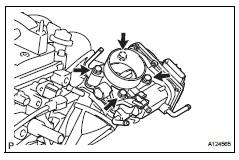
- Connect the fuel tube into the clamp.
- Connect the wire harness clamp.
- Connect the throttle position sensor and control motor connector.
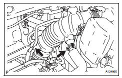
- Connect the no. 1 Throttle body hose to the throttle body
- Connect the no. 2 Water by-pass hose to the throttle body.
- Connect the water by-pass hose to the throttle body.
- Connect the purge line hose to the throttle body.
- Install air cleaner cap
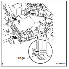
- Install the air cleaner filter element onto the air cleaner case.
- Insert the hinge part of the air cleaner cap into the air cleaner case, then hang the 2 hook clamps.
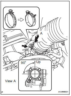
- Align the matchmarks of the no. 1 Air cleaner hose
and throttle body, and then connect the air cleaner
hose no. 1 To the throttle body and unfasten the no.
1 Air cleaner hose clamp.
Notice:
Make sure that the hose clamp is at the correct angle.
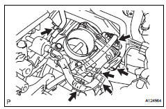
- Connect the purge line hose to the clamp.
- Connect the no. 2 Ventilation hose to the air cleaner hose.
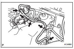
- Install the 4 wire harness clamps.
- Connect the mass air flow meter connector.
- Connect cable to negative battery terminal
- Add engine coolant (see page co-6)
- Check for engine coolant leakage (see page co-1)
- Install no. 1 Engine cover
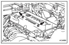
- Install the cover with the 2 nuts.
Torque: 7.0 N*m (71 kgf*cm, 62 in.*Lbf)
 Inspection
Inspect throttle body
Measure the resistance of the throttle control motor.
Standard resistance
If the result is not as specified, replace the throttle
body. ...
 Knock sensor
...
Other materials:
Air outlets and air flow
Upper body
Upper body and feet
Feet
Feet and windshield
Switching between outside air and recirculated air modes
Press .
The mode switches between outside air mode (indicator off) and recirculated
air mode (indicator on) each time
is pressed.
Adjusting the pos ...
Trouble in passenger airbag on / off indicator
Description
The occupant classification system detects the front passenger seat condition
and then indicates whether
the front passenger airbag is activated or not through the passenger airbag on /
off indicator
illumination.
The passenger airbag on / off indicator illumination changes dep ...
Reassembly (2006/01- )
Install drive shaft bearing case subassembly
(for rh)
Install the bearing snap ring.
Using sst and a press, press in the drive shaft
bearing case to the inboard joint rh.
Sst 09527-10011, 09710-04081
Notice:
The bearing should be installed completely.
Using a snap rin ...
