Toyota RAV4 (XA40) 2013-2018 Service Manual: Installation
Hint:
- Use the same procedures for the rh side and lh side.
- The procedures listed below are for the lh side.
- Install rear stabilizer bush
- Install the 2 bushes.
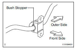
Hint:
- Install each bush to the outer side of the bush stopper on each stabilizer bar.
- Install each bush with its slit facing the vehicle front side.
- Install rear stabilizer bar
- Install the stabilizer bar to the vehicle.
Notice:
When installing the stabilizer bar, make sure not to damage the sensor wires, brake hoses, etc.
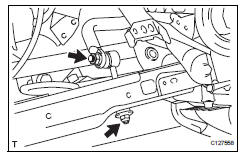
- Install rear no. 1 Stabilizer bar bracket
- Install the bracket with the 2 nuts.
Torque: 60 n*m (612 kgf*cm, 44 ft.*Lbf)
- Install rear coil spring insulator lower lh (see page sp-34)
- Install rear coil spring lh (see page sp-34)
- Install rear coil spring insulator upper lh (see page sp-34)
- Install rear coil spring insulator lower rh
Hint
Use the same procedures described for the lh side.
- Install rear co3h
Hint:
Use the same procedures described for the lh side.
- Install rear coil spring insulator upper rh
Hint:
Use the same procedures described for the lh side.
- Temporarily install rear no. 2 Suspension arm assembly lh (see page sp-46)
- Temporarily install rear no. 2 Suspension arm assembly rh
Hint:
Use the same procedures described for the lh side.
- Install rear stabilizer link assembly lh
- Install the stabilizer link with the 2 nuts.
Torque: 74 n*m (755 kgf*cm, 55 ft.*Lbf) for stabilizer bar
30 N*m (306 kgf*cm, 22 ft.*Lbf) for suspension no. 2 Arm
- Install rear stabilizer link assembly rh
Hint:
Use the same procedures described for the lh side.
- Install rear wheel
Torque: 103 n*m (1,050 kgf*cm, 76 ft.*Lbf)
- Stabilize suspension (see page sp-37)
- Tighten rear no. 2 Suspension arm assembly lh (see page sp-46)
- Tighten rear no. 2 Suspension arm assembly rh
Hint:
Use the same procedures described for the lh side.
- Inspect and adjust rear wheel alignment
- Inspect and adjust the rear wheel alignment (see page sp-7).
- Check speed sensor signal
- Check the speed sensor signal (see page bc-44).
 Inspection
Inspect rear stabilizer link assembly lh
As shown in the illustration, move the ball joint stud
back and forth 5 times before installing the nut.
Using a torque wrench, turn the nut c ...
 Drive shaft
...
Other materials:
Pig power supply voltage malfunction
Description
When a problem occurs in the system, the power source relay circuit is shut
off to stop the power assist.
Wiring diagram
Inspection procedure
Read value of intelligent tester (pig power supply)
Connect the intelligent tester (with can vim) to the
dlc3.
Turn ...
Data list / active test
Read data list
Hint:
Using the intelligent tester's data list allows switch,
sensor, actuator and other item values to be read without
removing any parts. Reading the data list early in
troubleshooting is one way to save time.
Connect the intelligent tester (with can vim) to the
dlc3 ...
Master cylinder pressure sensor malfunction
Description
The master cylinder pressure sensor is connected to the skid control ecu in
the abs and traction
actuator.
Dtc c1281/81 can be detected when the master cylinder pressure sensor sends a
master cylinder
pressure signal or test mode ends. Dtc c1281/81 is output only in test mo ...
