Toyota RAV4 (XA40) 2013-2018 Service Manual: Monitor drive pattern
- Test monitor drive pattern for ect
Caution:
Perform this drive pattern on a level surface and strictly observe the posted speed limits and traffic laws while driving.
Hint:
Performing this drive pattern is one method to simulate the ect's malfunction detection conditions.
The dtcs may not be detected through ordinary, everyday driving. Also, dtcs may not be detected through this drive pattern.
- Preparation for driving
- Warm up the engine sufficiently (engine coolant temperature is 60°c (140°f) or higher).
- Drive the vehicle when the atmospheric
temperature is -10°c (14°f) or higher.
Malfunction is not detected when the atmospheric temperature is less than -10°c (14°f).
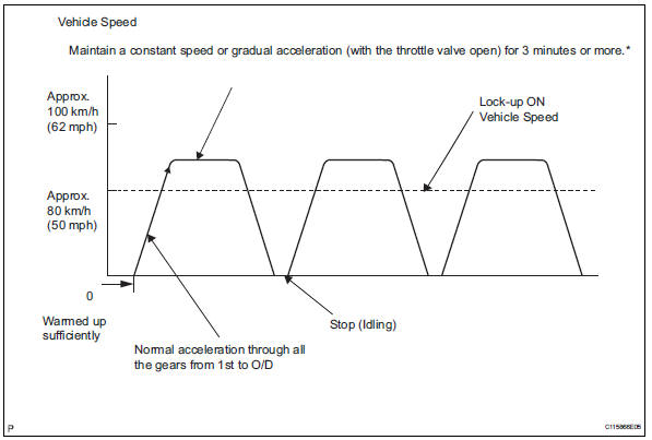
- Drive pattern
- Drive the vehicle through all the gears.
Stop→1st → 2nd →3rd → o/d → o/d (lock-up on).
- Repeat the above drive pattern 3 times or more.
Notice:
- When using the intelligent tester, the monitor status can be found in "enhanced obd ii / data list" or under "carb obd ii".
- In the event that the drive pattern must be interrupted (due to traffic conditions or other factors), the drive pattern can be resumed and, in most cases, the monitor can be completed.
Caution:
Perform this drive pattern on a level road as much as possible and strictly observe the posted speed limits and traffic laws while driving.
Hint:
*: Drive at such a speed in the uppermost gear to engage lock-up. The vehicle can be driven at a speed lower than the speed shown in the above diagram under the lock-up condition.
Notice:
It is necessary to drive the vehicle for approximately 30 minutes to detect dtc p0711 (transmission fluid temperature sensor "a" performance).
 Manual shifting test
Manual shifting test
Hint:
Through this test, it can be determined whether the
trouble occurs in the electrical circuit or if it is a
mechanical problem in the transaxle.
If any abnorm ...
 Problem symptoms table
Hint:
Use the table below to help determine the cause of the
problem symptom. The potential causes of the symptoms
are listed in order of probability in the "suspected area"
column ...
Other materials:
The rear cross traffic
alert function
The areas that vehicles can be detected in are outlined below.
The range of the detection area
extends to:
Approximately 11.5 Ft. (3.5 M)
from the side of the vehicle
The first 1.6 Ft. (0.5 M) from the
side of the vehicle is not in the
detection area
Approximately 9.8 Ft. (3 M) fr ...
Brk relay
On-vehicle inspection
Inspect brk relay
Remove the brk relay from the engine room no. 1
Relay block.
Measure the resistance of the relay.
Standard resistance
If the result is not as specified, replace the relay. ...
Refueling
Opening the fuel tank cap
Perform the following steps
to open the fuel tank cap:
Before refueling the vehicle
Close all the doors and windows,
and turn the engine
switch to OFF.
Confirm the type of fuel.
â– Fuel tank opening for unleaded
gasoline
To help prevent incorrect fueling,
your vehicle ...
