Toyota RAV4 (XA40) 2013-2018 Service Manual: Problem symptoms table
Hint:
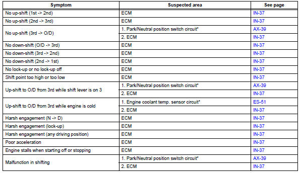
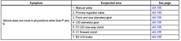
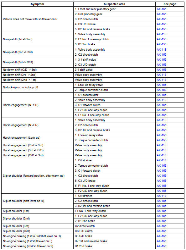
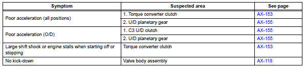
- Use the table below to help determine the cause of the problem symptom. The potential causes of the symptoms are listed in order of probability in the "suspected area" column of the table. Check each symptom by checking the suspected areas in the order they are listed. Replace parts as necessary.
- The matrix chart is divided into 2 chapters. When troubleshooting, check chapter 1 first. If instructions are given in chapter 1 to proceed to 2, proceed as instructed.
- If the instruction "proceed to next circuit inspection shown in problem symptoms table" is given in the flowchart for each circuit, proceed to the next suspected area in the table.
- If the problem still occurs even though there are no malfunctions in any of the circuits, check the ecm and replace it if necessary.
Chapter 1: electrical circuit matrix chart
Hint:
*: When the circuit is defective, a dtc may be output.
Chapter 2: on-vehicle repair and off-vehicle repair
 Monitor drive pattern
Test monitor drive pattern for ect
Caution:
Perform this drive pattern on a level surface and
strictly observe the posted speed limits and traffic
laws while driving.
Hint:
Performing this ...
 Terminals of ecm
Check ecm
Measure the voltage of the ecm connector.
Hint:
Each ecm terminal's standard voltage is shown in
the table below.
In the table, first follow the information under
" ...
Other materials:
Power steering ecu
Components
Removal
Disconnect cable from negative battery
terminal
Remove instrument panel sub-assembly
upper
Remove the instrument panel (see page ip-4).
Remove power steering ecu
Disconnect the 4 connectors.
Remove the 3 nuts and remove the power steering
e ...
Front drive shaft assembly (for 4wd)
Components (2005/11-2006/01)
Components (2006/01- )
...
How to proceed with troubleshooting
Hint:
Use the following procedures to troubleshoot the occupant
classification system.
*: Use the intelligent tester.
Vehicle brought to workshop
Passenger airbag on/off indicator check
Dtc check (present and past dtc)*
Check for dtcs (see page rs-249 ).
Result ...
