Toyota RAV4 (XA40) 2013-2018 Service Manual: Only rear door lh lock / unlock functions do not operate
Description
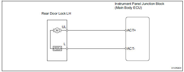
The main body ecu receives lock / unlock switch signals and activates the door lock motor accordingly.
Wiring diagram
Inspection procedure
- Inspect rear door with motor lock assembly lh
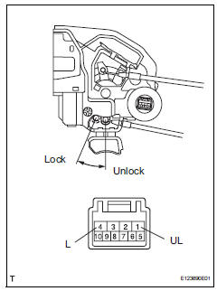
- Apply the battery voltage to the door lock motor and check the operation of the door lock motor.
Ok 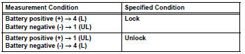

- Check wire harness (door lock - ecu)
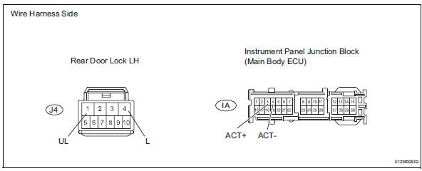
- Disconnect the j4 door lock connector.
- Disconnect the ia junction block connector.
- Measure the resistance of the wire harness side connectors.
Standard resistance 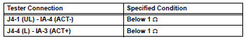

Replace instrument panel junction block (main body ecu)
 Only passenger door lock / unlock functions do not operate
Description
The main body ecu receives lock / unlock switch signals and activates the
door lock motor accordingly.
Wiring diagram
Inspection procedure
Read value of intelligent tester (lo ...
 Only rear door rh lock / unlock functions do not operate
Description
The main body ecu receives lock / unlock switch signals and activates the
door lock motor accordingly.
Wiring diagram
Inspection procedure
Inspect rear door with motor lock as ...
Other materials:
All doors cannot be locked / unlocked simultaneously
Description
The main body ecu receives switch signals from the door control switch on the
power window regulator
master switch, door control switch and driver side door key cylinder, and
activates the door lock motor on
each door accordingly.
Wiring diagram
Inspection procedure
Perf ...
Compressor and pulley (for 2az-fe)
Components
Removal
Discharge refrigerant from
refrigeration system (see page ac-172)
Disconnect cable from negative battery
terminal
Caution:
Wait at least 90 seconds after disconnecting the
cable from the negative (-) battery terminal to
prevent airbag and seat belt pretensione ...
How to proceed with troubleshooting
Hint:
*: Use the intelligent tester.
Hint:
If the display indicates a communication fault in the tester,
inspect the dlc3.
Hint:
Record or print dtcs and freeze frame data, if necessary.
Hint:
If the engine does not start, first perform the "check dtc"
procedures a ...
