Toyota RAV4 (XA40) 2013-2018 Service Manual: Problem symptoms table (2006/01- )
Hint:
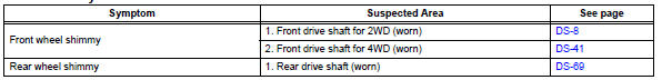
Use the table below to help determine the cause of the problem symptom. The potential causes of the symptoms are listed in order of probability in the "suspected area" column of the table. Check each symptom by checking the suspected areas in the order they are listed. Replace parts as necessary.
Drive shaft system
 Problem symptoms table (2005/11-2006/01)
Hint:
Use the table below to help determine the cause of the
problem symptom. The potential causes of the symptoms are
listed in order of probability in the "suspected area" column of
th ...
 Front drive shaft assembly (for 2wd)
Components (2005/11-2006/01)
Components (2006/01- )
...
Other materials:
Evaporative emission system reference orifice
Dtc summary
Hint:
The reference orifice is located inside the canister pump module.
Description
The description can be found in the evap (evaporative emission) system (see
page es-335).
Inspection procedure
Refer to the evap system (see page es-340).
Monitor description
5 Hours* af ...
Fuel pump control circuit
Description
When the engine is cranked, the starter relay drive signal output from the
star terminal of the ecm is
input into the sta terminal of the ecm, and ne signal generated by the
crankshaft position sensor is also
input into the ne+ terminal. Thus, the ecm interprets that the engine is ...
Terminals of ecm
Check ecm
Disconnect the a9 and b30 connectors.
Measure the voltage and resistance of the wire
harness side connectors.
If the result is not as specified, there may be a
malfunction on the wire harness side. ...
