Toyota RAV4 (XA40) 2013-2018 Service Manual: Rear axle hub and bearing
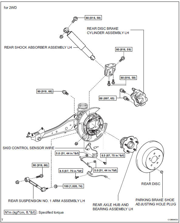
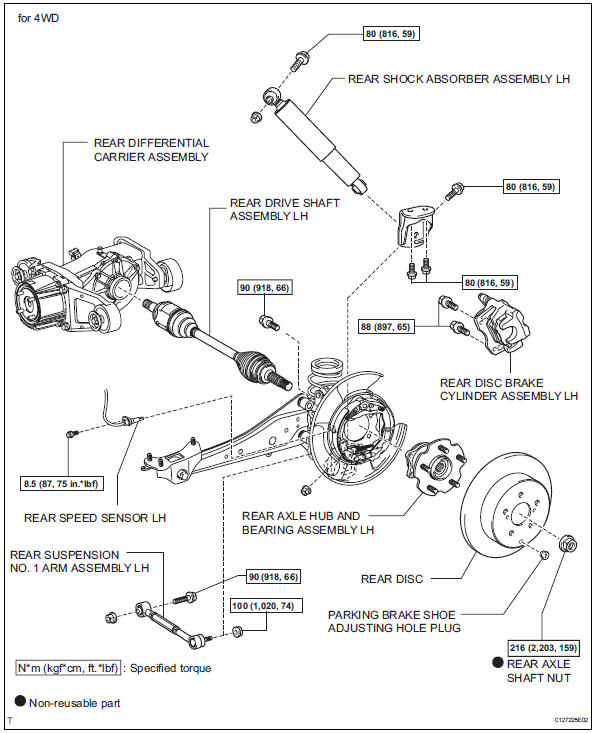
Components
On-vehicle inspection
- Remove rear wheel
- Disconnect rear drive shaft assembly lh (for 4wd)
- Disconnect the drive shaft (see page ds-69).
- Remove rear disc brake cylinder assembly lh (see page br-55)
- Remove rear disc (see page br-57)
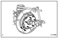
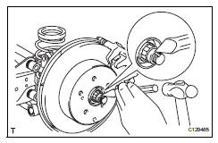
- Check bearing backlash and axle hub deviation
- Using a dial indicator, measure the backlash near the center of the axle hub.
Maximum backlash: 0.05 Mm (0.0020 In.)
If the backlash is greater than the maximum, replace the axle hub.
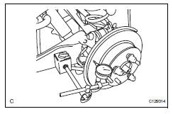
- Using a dial indicator, measure the disc runout 10 mm (0.39 In.) Inside the outer edge of the disc.
Maximum deviation: 0.08 Mm (0.0031 In.) For 2wd
0.06 Mm (0.0024 In.) For 4wd
Notice:
If the runout exceeds the maximum, change the installation positions of the rear disc and axle hub so that the runout will be as low as possible. If the runout exceeds the maximum even when the installation positions are changed, shave the rear disc. If the rear disc needs to be shaved to less than the minimum, replace the rear disc. If the rear disc is replaced, perform the runout inspection again. If the runout still exceeds the maximum, replace the hub and bearing with a new one.
Removal
- Remove rear wheel
- Disconnect cable from negative battery terminal
Caution:
Wait at least 90 seconds after disconnecting the cable from the negative (-) battery terminal to prevent airbag and seat belt pretensioner activation.
- Remove rear axle shaft nut (for 4wd)
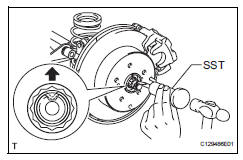
- Using sst and hammer, unstake the staked part of the nut.
Sst 09930-00010
Notice:
Loosen the staked part of the nut completely, otherwise the screw of the drive shaft may be damaged.
- While applying the brake, remove the lock axle hub nut.
- Remove rear disc brake cylinder assembly lh (see page br-55)
- Remove rear disc (see page br-57)
- Remove skid control sensor wire (for 2wd) (see page bc-198)
- Remove rear speed sensor lh (for 4wd) (see page bc-205)
- Remove rear suspension no. 1 Arm assembly lh (see page sp-42)
- Disconnect rear shock absorber assembly lh
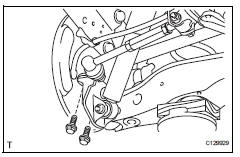
- Remove the 2 bolts and disconnect the shock absorber with bracket from the axle carrier.
- Remove rear axle hub and bearing assembly lh
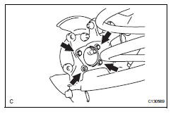
- Fro 2wd:
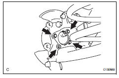
- Remove the 4 bolts, and axle hub and the bearing from the axle carrier.
Notice:
Do not place the hub and bearing's magnet rotor side so that it is facing downward, and do not allow the magnet rotor side to become damaged or contact foreign matter.
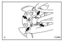
- For 4wd:
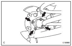
- Put matchmarks on the drive shaft and the axle hub and bearing.
- Remove the 4 bolts, and the axle hub and bearing from the axle carrier.
Notice:
Do not place the hub and bearing's magnet rotor side so that it is facing downward, and do not allow the magnet rotor side to become damaged or contact foreign matter.
Installation
- Install rear axle hub and bearing assembly lh
- For 2wd:
- Install the axle hub and bearing to the axle carrier with the 4 bolts.
Torque: 90 n*m (918 kgf*cm, 68 ft.*Lbf)
Notice:
Do not place the hub and bearing's magnet rotor side so that it is facing downward, and do not allow the magnet rotor side to become damaged or contact foreign matter.
- Fro 4wd:
- Align the shaft splines and drive in the drive shaft to the axle hub and bearing.
- Install the axle hub and bearing assembly to the axle carrier with the 4 bolts.
Torque: 90 n*m (918 kgf*cm, 68 ft.*Lbf)
Notice:
Do not place the hub and bearing's magnet rotor side so that it is facing downward, and do not allow the magnet rotor side to become damaged or contact foreign matter.
- Connect rear shock absorber assembly lh
- Install the shock absorber to the axle carrier with bracket with the 2 bolts.
- Temporarily install rear suspension no. 1 Arm assembly lh (see page sp-43)
- Install skid control sensor wire (for 2wd) (see page bc-201)
- Install rear speed sensor lh (for 4wd) (see page bc-206)
- Install rear disc (see page br-58)
- Install rear brake cylinder assembly lh (see page br-61)
- Install rear axle shaft nut (for 4wd)
- Install a new hub nut.
Torque: 216 n*m (2,203 kgf*cm, 159 ft.*Lbf)
- Using a chisel and hammer, stake the hub nut.
- Install rear wheel
Torque: 103 n*m (1,050 kgf*cm, 76 ft.*Lbf)
- Stabilize suspension (see page sp-37)
- Tighten front shock absorber assembly lh (see page sp-37)
- Tighten rear suspension no. 1 Arm assembly lh (see page sp-43)
- Inspect rear wheel alignment
- Inspect the rear wheel alignment (see page sp-7).
- Connect cable to negative battery terminal
- Check speed sensor signal
- Check the speed sensor signal (see page bc-44).
 Rear axle hub bolt
Components
Replacement
Hint:
Use the same procedures for the rh side and lh side.
The procedures listed below are for the lh side.
Remove rear wheel
Remove rear disc brake cylinder ...
 Tire and wheel
...
Other materials:
Installation
Hint:
Use the same procedures for the rh side and lh side.
The procedures listed below are for the lh side.
Install rear door belt moulding assembly
lh
Attach the claws to install the moulding.
Hint:
Confirm that the moulding is firmly installed.
Install rear door tr ...
Components
...
Screen for general settings
Press the “setup” button.
Select “general” on the “setup”
screen.
‚ÄúEnglish‚Äù, ‚Äúfrançais‚Äù or
‚Äúespañol‚Äù can be selected.
On/off can be selected to
sound beeps.
Select to change the screen
color.
Select to change the keyboard
layout.
...
