Toyota RAV4 (XA40) 2013-2018 Service Manual: Evaporative emission system switching valve control
Dtc summary
Hint:
The vent valve is built into the canister pump module.
Description
The description can be found in the evap (evaporative emission) system (see page es-335).
Inspection procedure
Refer to the evap system (see page es-340).
Monitor description
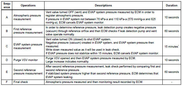
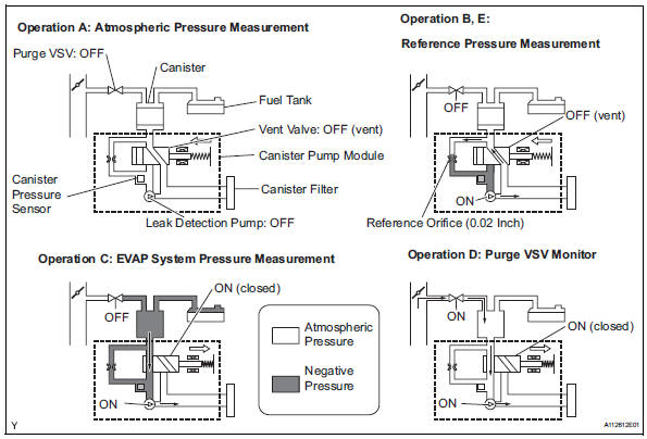
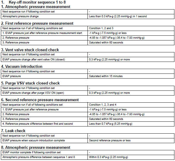
5 Hours* after the ignition switch is turned off, the leak detection pump creates negative pressure (vacuum) in the evap system. The ecm monitors for leaks and actuator malfunctions based on the evap pressure.
Hint:
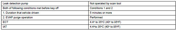
*: If the engine coolant temperature is not below 35°c (95°f) 5 hours after the ignition switch is turned off, the monitor check starts 2 hours later. If it is still not below 35°c (95°f) 7 hours after the ignition switch is turned off, the monitor check starts 2.5 Hours later.

*: If only a small amount of fuel is in the fuel tank, it takes longer for the evap pressure to stabilize.
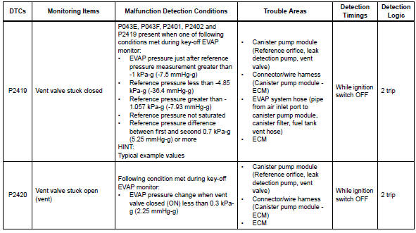
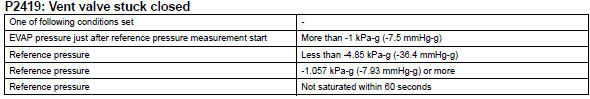
- P2419: vent valve stuck closed
In operation b, the leak detection pump creates negative pressure (a vacuum) through the reference orifice. The evap system pressure is then measured by the ecm, using the canister pressure sensor, to determine the reference pressure. If the pressure exceeds -1.057 Kpa-g (-7.93 Mmhg-g) 4 seconds after the leak detection pump is turned on, the ecm interprets this as the vent valve being stuck closed.
The ecm illuminates the mil and sets the dtc (2 trip detection logic).
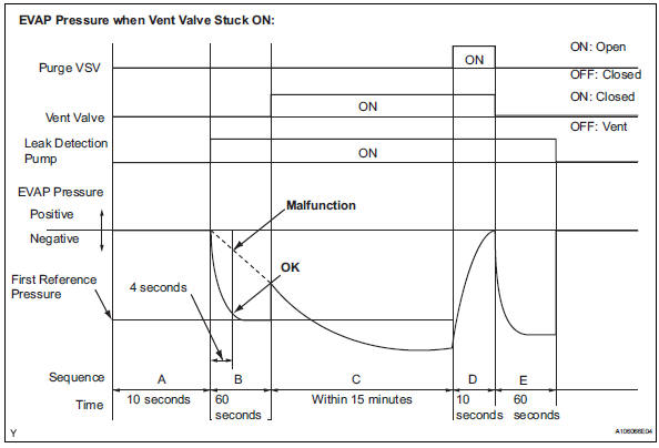
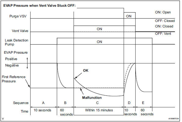
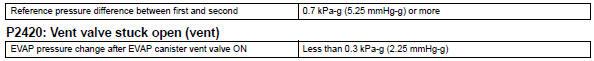
- P2420: vent valve stuck open (vent)
In operation c, the vent valve turns on (closes) and the evap system pressure is then measured by the ecm, using the canister pressure sensor, to conduct an evap leak check. If the pressure does not increase when the vent valve is open, the ecm interprets this as the vent valve being stuck open. The ecm illuminates the mil and sets the dtc.
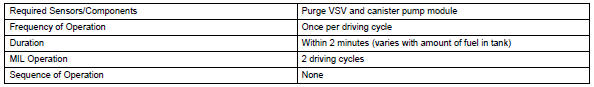
Monitor strategy
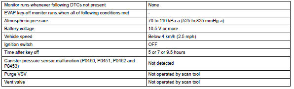
Typical enabling conditions
Typical malfunction thresholds
"Saturated" indicates that the evap pressure change is less than 0.286 Kpa-g (2.14 Mmhg-g) in 60 seconds.
Monitor result
Refer to checking monitor status (see page es-17).
 Evaporative emission leak detection pump
Dtc summary
Hint:
The leak detection pump is built into the canister pump module.
Description
The description can be found in the evap (evaporative emission) system (see
page es-335).
I ...
 Ecm / pcm internal engine off timer performance
Dtc summary
Description
To ensure the accuracy of the evap (evaporative emission) monitor values, the
soak timer, which is built
into the ecm, measures 5 hours (+-15 minutes) from when th ...
Other materials:
Maintenance requirements
To ensure safe and economical driving, day-to-day care and regular
maintenance are essential. It is the owner’s responsibility to
perform regular checks. Toyota recommends the following maintenance:
General maintenance
General maintenance should be performed on a daily basis. This can
be done ...
Ecm communication stop mode (2005/11-2006/01)
Description
Wiring diagram
Inspection procedure
Notice:
Turn the ignition switch off before measuring the resistances of the
main wire and the branch
wire.
After the ignition switch is turned off, check that the key reminder
warning system and light
reminder warning system ...
How to proceed with troubleshooting
Hint:
Use these procedures to troubleshoot the engine immobiliser
system.
*: Use the intelligent tester.
Vehicle brought to workshop
Inspect battery voltage
Standard voltage:
11 to 14 v
If the voltage is below 11 v, recharge or replace the battery
before proceeding.
cran ...
