Toyota RAV4 (XA40) 2013-2018 Service Manual: Ecm / pcm internal engine off timer performance

Dtc summary
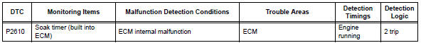
Description
To ensure the accuracy of the evap (evaporative emission) monitor values, the soak timer, which is built into the ecm, measures 5 hours (+-15 minutes) from when the ignition switch is turned off, before the monitor is run. This allows the fuel to cool down, which stabilizes the evap pressure. When 5 hours have elapsed, the ecm turns on.
Monitor description
5 Hours after the ignition switch is turned off, the soak timer activates the ecm to begin the evap system monitor. While the engine is running, the ecm monitors the synchronization of the soak timer and the cpu clock. If these two are not synchronized, the ecm interprets this as a malfunction, illuminates the mil and sets the dtc (2 trip detection logic).
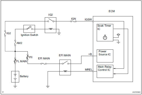
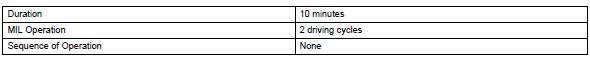
Monitor strategy
![]()
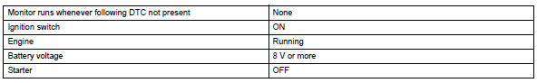
Typical enabling conditions
Typical malfunction thresholds
![]()
Inspection procedure
Hint:
- Dtc p2610 is set if an internal ecm problem is detected. Diagnostic
procedures are not required.
Ecm replacement is necessary.
- Read freeze frame data using the intelligent tester. Freeze frame data records the engine condition when malfunctions are detected. When troubleshooting, freeze frame data can help determine if the vehicle was moving or stationary, if the engine was warmed up or not, if the air-fuel ratio was lean or rich, and other data from the time the malfunction occurred.
- Replace ecm
- Replace the ecm (see page es-429).

- Check whether dtc output recurs
- Connect the intelligent tester to the dlc3.
- Turn the ignition switch on.
- Turn the tester on.
- Clear dtcs (see page es-35).
- Start the engine and wait for 10 minutes or more.
- On the tester, select the following menu items: diagnosis / enhanced obd ii / dtc info / pending codes.
- If no pending dtc is displayed, the repair has been successfully completed.

 Evaporative emission system switching valve control
Dtc summary
Hint:
The vent valve is built into the canister pump module.
Description
The description can be found in the evap (evaporative emission) system (see
page es-335).
Inspection ...
 A/f sensor circuit slow response (bank 1 sensor 1)
Hint:
Sensor 1 refers to the sensor mounted in front of the three-way catalytic
converter (twc) and located
near the engine assembly.
Description
Refer to dtc p2195 (see page es-292).
M ...
Other materials:
Lumbar support adjuster assembly
Inspection
Inspect lumbar support adjuster assembl
Check operation of the lumbar support adjuster.
Check if the lumbar support adjuster moves
smoothly when the battery is connected to the
lumbar support adjuster motor connector
terminals.
Ok
If the result is not as spec ...
Removal (2006/01- )
Disconnect cable from negative battery
terminal
Caution:
Wait at least 90 seconds after disconnecting the
cable from the negative (-) battery terminal to
prevent airbag and seat belt pretensioner activation.
Remove roof headlining assembly
Remove the roof headlining (see page ir ...
Problem symptoms table (2005/11-2006/01)
Hint:
Use the table below to help determine the cause of the
problem symptom. The potential causes of the symptoms are
listed in order of probability in the "suspected area" column of
the table. Check each symptom by checking the suspected
areas in the order they are listed. Replace p ...
