Toyota RAV4 (XA40) 2013-2018 Service Manual: Evaporative emission leak detection pump
Dtc summary
Hint:
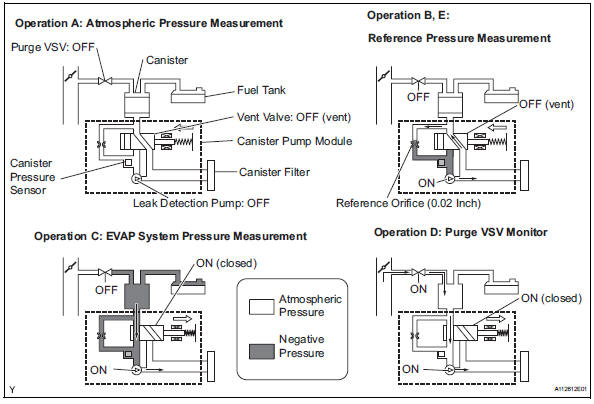
The leak detection pump is built into the canister pump module.
Description
The description can be found in the evap (evaporative emission) system (see page es-335).
Inspection procedure
Refer to the evap system (see page es-340).
Monitor description
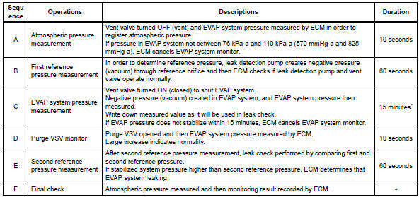
5 Hours* after the ignition switch is turned off, the leak detection pump creates negative pressure (vacuum) in the evap system. The ecm monitors for leaks and actuator malfunctions based on the evap pressure.
Hint:
*: If the engine coolant temperature is not below 35°c (95°f) 5 hours after the ignition switch is turned off, the monitor check starts 2 hours later. If it is still not below 35°c (95°f) 7 hours after the ignition switch is turned to off, the monitor check starts 2.5 Hours later.
![]()
*: If only a small amount of fuel is in the fuel tank, it takes longer for the evap pressure to stabilize.
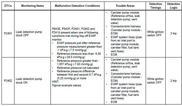
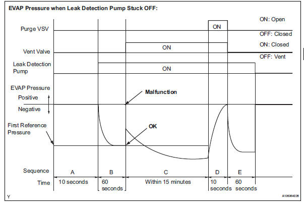
- P2401: leak detection pump stuck off in operation b, the leak detection pump creates negative pressure (a vacuum) through the reference orifice. The evap system pressure is then measured by the ecm, using the canister pressure sensor, to determine the reference pressure. If the pressure is higher than -1.057 Kpa-g (-7.93 Mmhg-g), or lower than -4.85 Kpa-g (-36.4 Mmhg-g), the ecm interprets this as the leak detection pump being stuck off (not operating). The ecm illuminates the mil and sets the dtc (2 trip detection logic).
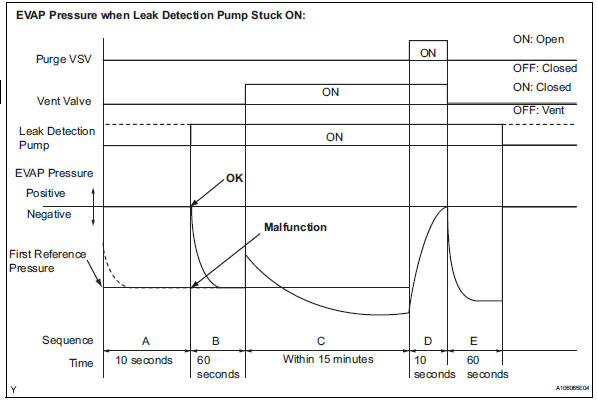
- P2402: leak detection pump stuck on in operation b, the leak detection pump creates negative pressure (a vacuum) through the reference orifice. The evap (evaporative emission) system pressure is then measured by the ecm, using the canister pressure sensor, to determine the reference pressure. If the pressure is higher than -1.057 Kpa-g (-7.93 Mmhg-g), or lower than -4.85 Kpa-g (-36.4 Mmhg-g), the ecm interprets this as the leak detection pump being stuck on (remaining on all the time). The ecm illuminates the mil and sets the dtc (2 trip detection logic).
Hint:
The detection logic of dtcs p2401 and p2402 is the same because in both cases the reference pressure measured in operation b is compared to the atmospheric pressure registered in operation a.
The ecm calculates the difference between these pressures by deducting [the reference pressure] from [the stored atmospheric pressure], and uses this to monitor the evap system pressure change.
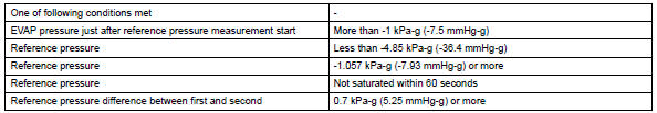
Monitor strategy
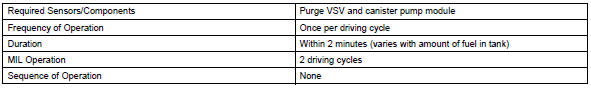
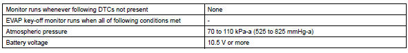
Typical enabling conditions
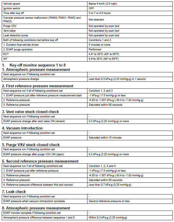
Typical malfunction thresholds
"Saturated" indicates that the evap pressure change is less than 0.286 Kpa-g (2.14 Mmhg-g) in 60 seconds.
Monitor result
Refer to checking monitor status (see page es-17).
 Oxygen (a/f) sensor pumping current circuit
Description
Refer to dtc p2195 (see page es-292).
Monitor description
The air-fuel ratio (a/f) sensor varies its output voltage in proportion to
the air-fuel ratio. If the a/f sensor
imp ...
 Evaporative emission system switching valve control
Dtc summary
Hint:
The vent valve is built into the canister pump module.
Description
The description can be found in the evap (evaporative emission) system (see
page es-335).
Inspection ...
Other materials:
Rear speed sensor (for 4wd)
Components
Removal
Hint:
Use the same procedures for the lh side and rh side.
The procedures listed below are for the lh side.
Disconnect cable from negative battery
terminal
Caution:
Wait at least 90 seconds after disconnecting the
cable from the negative (-) battery termin ...
On-vehicle inspection
Check fan and generator v belt
Visually check the drive belt for excessive wear,
frayed cords, etc.
If any defect has been found, replace the drive belt.
Hint:
Cracks on the rib side of a drive belt are considered
acceptable.
If the drive belt has chunks missing from the r ...
Opening/closing the back
door (vehicles with power
back door)
â– Using the wireless remote
control
Press and hold the switch.
The power back door automatically
opens/closes.
Pressing the switch while the power
back door is opening/closing stops
the operation. When the switch is
pressed and held again during the
halted operation, the back door will
perform t ...
