Toyota RAV4 (XA40) 2013-2018 Service Manual: Ambient temperature sensor circuit
![]()
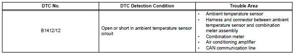
Description
The ambient temperature sensor is installed in the front part of the condenser to detect the ambient temperature and control the air conditioner. The sensor is connected to the combination meter and detects fluctuations in the ambient temperature. This data is used for controlling the room temperature.
The sensor sends a signal to the air conditioning amplifier via the combination meter. The resistance of the ambient temperature sensor changes in accordance with the ambient temperature. As the temperature decreases, the resistance increases. As the temperature increases, the resistance decreases.
The air conditioning amplifier applies a voltage (5 v) to the ambient temperature sensor and reads voltage changes as changes in the resistance of the ambient temperature sensor. The combination meter sends the read signal to the air conditioning amplifier via can communication.
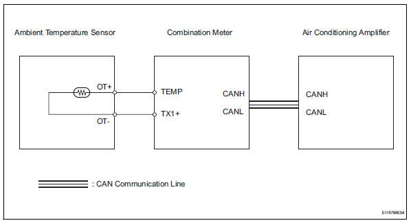
Wiring diagram
Inspection procedure
- Read value of intelligent tester (ambi temp sens)
- Connect the intelligent tester (with can vim) to the dlc3.
- Turn the ignition switch on and turn the intelligent tester main switch on.
- Select the item below in the data list, and read the value displayed on the intelligent tester.
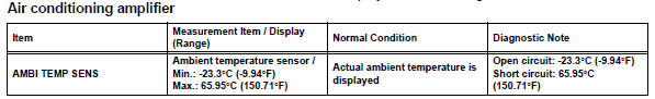
Ok: the display is as specified in the normal condition column.

- Inspect ambient temperature sensor
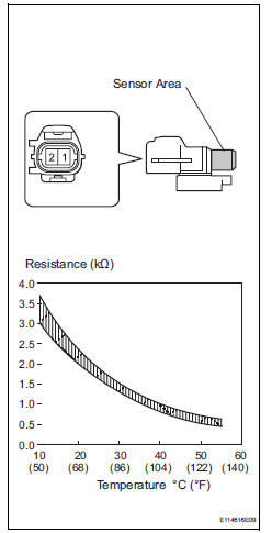
- Remove the ambient temperature sensor.
- Measure the resistance of the sensor.
Standard resistance 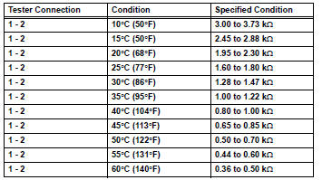
Notice:
- Touching the sensor even slightly may change the resistance value. Be sure to hold the connector of the sensor.
- When measuring, the sensor temperature must be the same as the ambient temperature.
Hint:
As the temperature increases, the resistance decreases (see the graph).

- Check wire harness (ambient temperature sensor - combination meter)
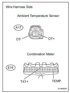
- Disconnect the a17 sensor connector.
- Disconnect the e19 meter connector.
- Measure the resistance of the wire harness side connectors.
Standard resistance 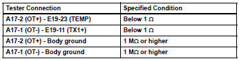

Replace combination meter
 Room temperature sensor circuit
Description
The room temperature sensor is installed in the instrument panel to detect
the room temperature and
control the heater and air conditioner auto mode. The resistance of the room
t ...
 Evaporator temperature sensor circuit
Description
The no. 1 Cooler thermistor (evaporator temperature sensor) is installed on
the evaporator in the air
conditioning unit to detect the temperature of the cooled air that has passed ...
Other materials:
Short in front passenger side curtain shield squib circuit
Description
The front passenger side curtain shield squib circuit consists of the center
airbag sensor and the curtain
shield airbag rh.
The circuit instructs the srs to deploy when the deployment conditions are met.
These dtcs are recorded when a malfunction is detected in the front p ...
Air mix damper control servo motor circuit (driver
side)
Description
The air mix damper servo sends pulse signals to indicate the damper position
to the air conditioning
amplifier. The air conditioning amplifier activates the motor (normal or
reverse) based on these signals to
move the air mix damper (driver seat) to the appropriate position. T ...
Dtc check / clear
Check dtc
When using intelligent tester:
Connect the intelligent tester (with can vim) to
the dlc3.
Turn the ignition switch on and press the
intelligent tester main switch on.
Read the dtcs by following the prompts on the
intelligent tester.
Hint:
Refer to the intel ...
