Toyota RAV4 (XA40) 2013-2018 Service Manual: Room temperature sensor circuit
![]()
Description
The room temperature sensor is installed in the instrument panel to detect the room temperature and control the heater and air conditioner auto mode. The resistance of the room temperature sensor changes in accordance with the room temperature. As the temperature decreases, the resistance increases. As the temperature increases, the resistance decreases.
The air conditioning amplifier applies a voltage (5 v) to the room temperature sensor and reads voltage changes as changes in the resistance of the room temperature sensor.
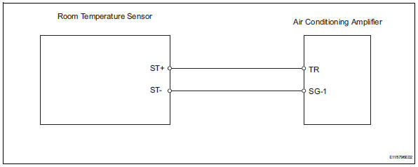
Wiring diagram
Inspection procedure
- Read value of intelligent tester (room temp)
- Connect the intelligent tester (with can vim) to the dlc3.
- Turn the ignition switch on and turn the intelligent tester main switch on.
- Select the item below in the data list, and read the value displayed on the intelligent tester.
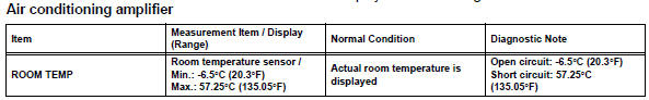
Ok: the display is as specified in the normal condition column.

- Inspect cooler thermistor (room temperature sensor)
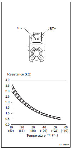
- Remove the room temperature sensor.
- Measure the resistance of the sensor.
Standard resistance 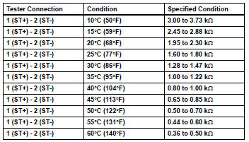
Notice:
- Touching the sensor even slightly may change the resistance value. Be sure to hold the connector of the sensor.
- When measuring, the sensor temperature must be the same as the ambient temperature.
Hint:
As the temperature increases, the resistance decreases (see the graph).

- Check wire harness (room temperature sensor - air conditioning amplifier)
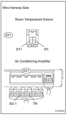
- Disconnect the e21 sensor connector.
- Disconnect the e37 amplifier connector.
- Measure the resistance of the wire harness side connectors.
Standard resistance 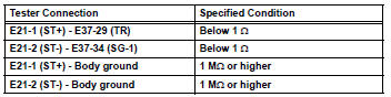

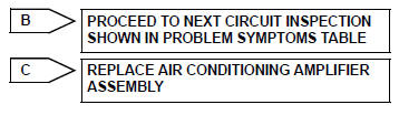
Replace air conditioning amplifier assembly
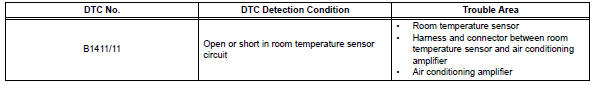
 Diagnostic trouble code chart (2006/01- )
Hint:
When the air conditioning system functions properly, dtc
b1400/00 is output.
Hint:
*1: Dtc b1422/22 (compressor lock sensor circuit) is
indicated only for a currently occurring malf ...
 Ambient temperature sensor circuit
Description
The ambient temperature sensor is installed in the front part of the
condenser to detect the ambient
temperature and control the air conditioner. The sensor is connected to the
c ...
Other materials:
Usb port/aux port
Connect an ipod, usb memory device or portable audio player
to the usb/aux port as indicated below. Select “ipod”, “usb” or
“aux” on the audio source selection screen and the device can
be operated via audio system.
Connecting using the usb/aux port
Ipod
Open the cover and connect ...
Parts location
System diagram
...
Throttle actuator control throttle body range / performance
Description
The electronic throttle control system (etcs) is composed of the throttle
actuator, throttle position (tp)
sensor, accelerator pedal position (app) sensor, and ecm. The ecm operates the
throttle actuator to
regulate the throttle valve in response to driver inputs. The tp senso ...
