Toyota RAV4 (XA40) 2013-2018 Service Manual: Removal (2006/01- )
- Disconnect cable from negative battery terminal
Caution:
Wait at least 90 seconds after disconnecting the cable from the negative (-) battery terminal to prevent airbag and seat belt pretensioner activation.
- Remove roof headlining assembly
- Remove the roof headlining (see page ir-37).
- Remove sliding roof side garnish lh
- Using a screwdriver, detach the claws and remove the garnish.
Hint:
Tape the screwdriver tip before use.
- Remove sliding roof side garnish rh
Hint:
Use the same procedures described for the lh side.
- Remove sliding roof glass sub-assembly
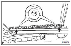
- Using a t25 "torx" driver, remove the 4 screws and glass.
- Pull the glass upward to remove it.
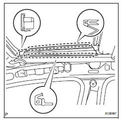
- Remove sliding roof weatherstrip
- Disconnect sliding roof drain hose
- Disconnect the 4 drain hoses.
- Remove sliding roof housing assembly
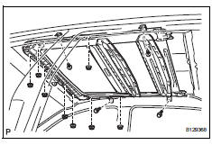
- Remove the 4 bolts, 8 nuts and housing.
Notice:
Be careful not to damage the curtain shield airbag when removing the housing.
 Removal (2005/11-2006/01)
Disconnect cable from negative battery
terminal
Caution:
Wait at least 90 seconds after disconnecting the
cable from the negative (-) battery terminal to
prevent airbag and seat belt preten ...
 Disassembly
Remove sliding roof drive gear subassembly
Remove the claw and room light bracket.
Remove the 2 bolts and drive gear.
Remove sliding roof drain hose joint lh
Rem ...
Other materials:
Removal
Disconnect cable from negative battery
terminal
Caution:
Wait at least 90 seconds after disconnecting the
cable from the negative (-) battery terminal to
prevent airbag and seat belt pretensioner activation.
Remove no. 1 Engine under cover
Remove front fender apron rh
Remove radia ...
The rear cross traffic alert function detection areas
The areas that vehicles can be detected in are outlined below.
To give the driver a more consistent time to react, the buzzer can alert
for faster vehicles from farther away.
Example:
The rear cross traffic alert function is operational when
The bsm main switch is set to on.
The shift ...
Installation
Install camshaft timing oil control valve
assembly
Apply a light coat of engine oil to the o-ring of the oil
control valve.
Install the oil control valve with the bolt.
Torque: 9.0 N*m (92 kgf*cm, 80 in.*Lbf)
Notice:
Make sure that the o-ring is not cracked or
jammed.
Co ...
