
Toyota RAV4 (XA40) 2013-2018 Service Manual: System diagram
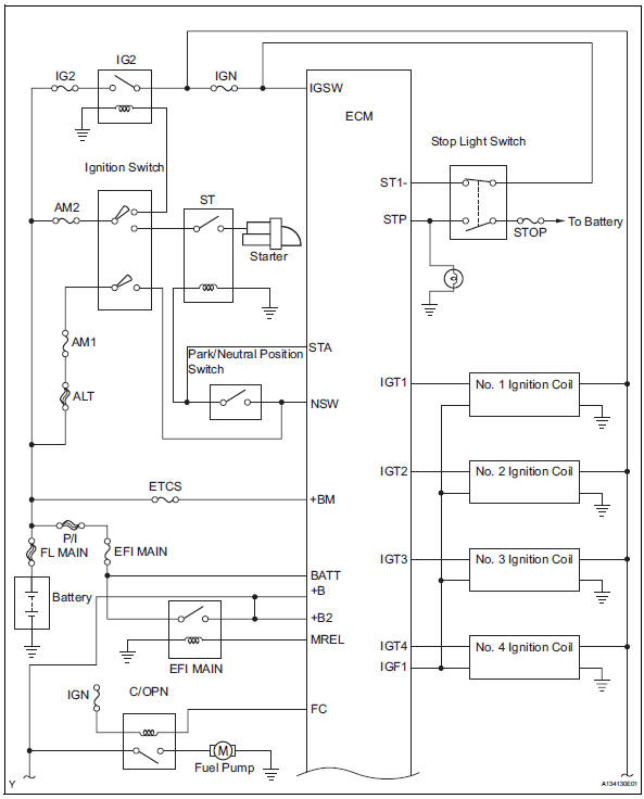
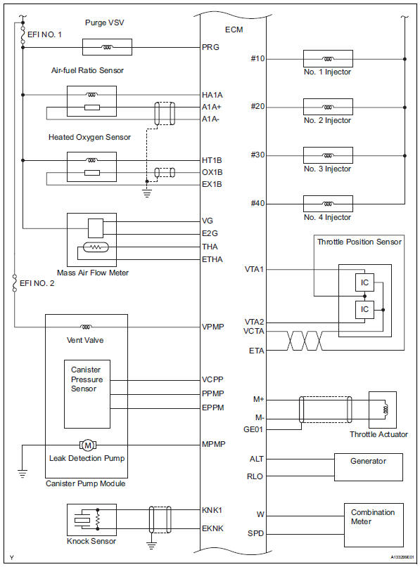
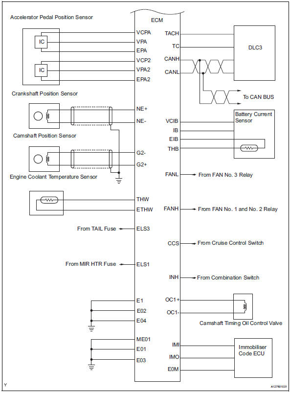
 Parts location
...
 How to proceed with troubleshooting
Hint:
*: Use the intelligent tester.
Hint:
If the display indicates a communication fault in the tester,
inspect the dlc3.
Hint:
Record or print dtcs and freeze frame data, if necessary. ...
Other materials:
Luggage compartment features
Cargo hooks
Raise the hook to use.
The cargo hooks are provided for
securing loose items.
WARNING
â– When cargo hooks are not in
use
To avoid injury, always return the
hooks to their stowed positions
when not in use.
Deck board
â– Flipping the deck board
upside down
The deck board can be flipped
...
Room temperature sensor (for automatic ai conditioning system)
Components
Removal
Remove lower instrument panel
Remove the lower instrument panel (see page ip-
16).
Remove room temperature sensor
Disconnect the duct.
Disconnect the connector.
Detach the claws and remove the sensor.
Inspection
Inspect room temperature ...
Headlight relay circuit
Description
When the light control switch, located on the headlight dimmer switch, is
turned to the head position, the
head relay illuminates the headlights.
Wiring diagram
Inspection procedure
Perform active test by intelligent tester (headlight)
Connect the intelligent tester ( ...
