Toyota RAV4 (XA40) 2013-2018 Service Manual: System diagram
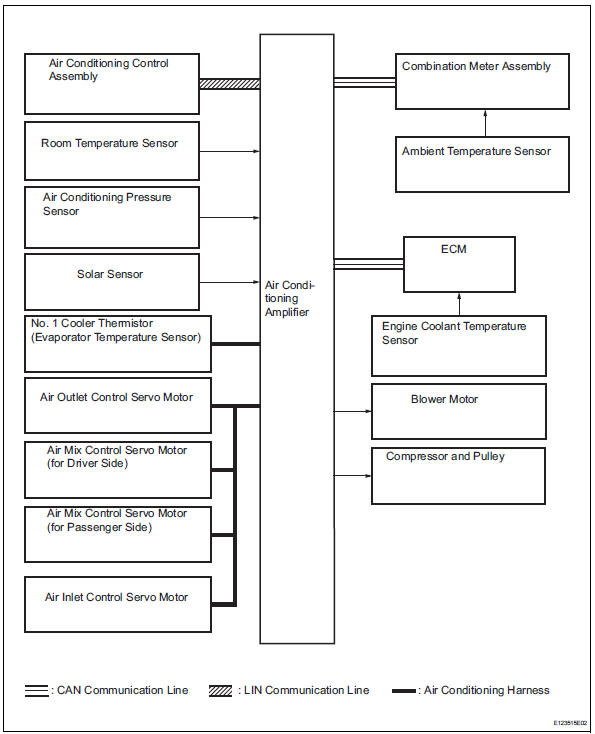
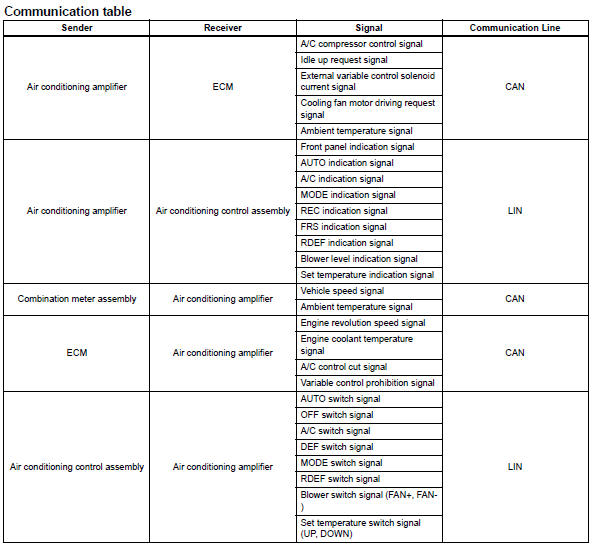
System diagram (2005/11-2006/01)
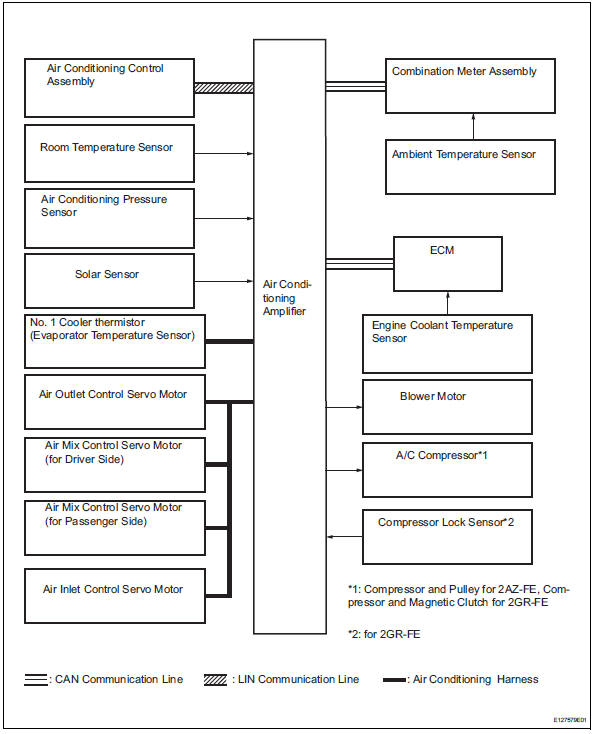
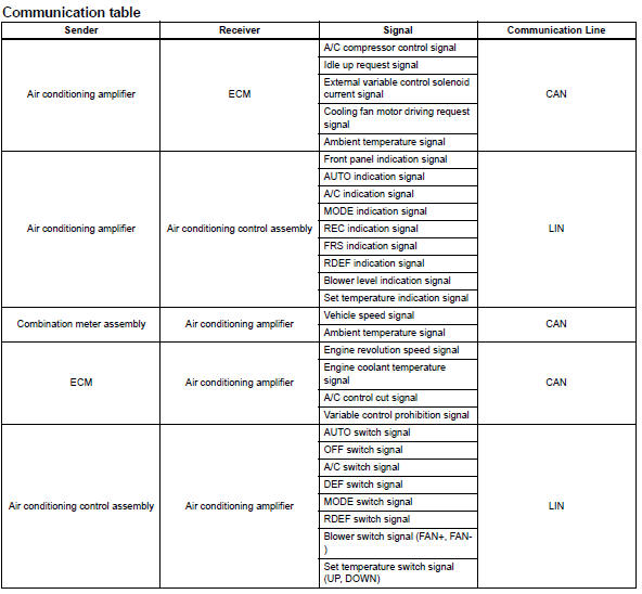
System diagram (2006/01- )

 System description
General
The air conditioning system has the following
features:
In accordance with the temperature set using the
temperature control switch, the air conditioning
amplifier determi ...
Other materials:
If the vehicle is submerged
or water on the road is rising
This vehicle is not designed
to be able to drive on roads
that are deeply flooded with
water. Do not drive on roads
where the roads may be
submerged or the water
may be rising. It is dangerous
to remain in the vehicle,
if it is anticipated that the
vehicle will be flooded or
set adrift. Remain calm ...
Rear seats
Reclining adjustments and
folding the seatbacks can
be done with lever operation.
Adjustment procedure
Pull the seatback angle adjustment
lever A, and adjust the
seatback angle.
WARNING
â– When operating the seatback
Observe the following precautions.
Failure to do so may cause death
or serious in ...
Installation
Install water pump assembly
Remove any old seal packing material from the
contact surface.
Apply a continuous line of seal packing as shown in
the illustration.
Seal packing:
toyota genuine seal parking black, three
bond 1207b or equivalent
Standard seal diameter:
2.2 To 2. ...
