Toyota RAV4 (XA40) 2013-2018 Service Manual: Throttle actuator control motor circuit
Description
The throttle actuator is operated by the ecm and opens and closes the throttle valve using gears.
The opening angle of the throttle valve is detected by the throttle position (tp) sensor, which is mounted on the throttle body. The tp sensor provides feedback to the ecm. This feedback allows the ecm to appropriately control the throttle actuator and monitor the throttle opening angle as the ecm responds to driver inputs.
Hint:
This etcs (electronic throttle control system) does not use a throttle cable.
Monitor description
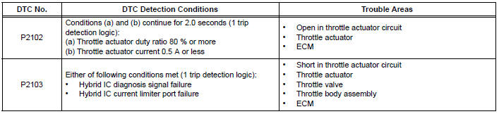
The ecm monitors the electrical current through the electronic actuator, and detects malfunctions and open circuits in the throttle actuator based on this value. If the current is outside the standard range, the ecm determines that there is a malfunction in the throttle actuator. In addition, if the throttle valve does not function properly (for example, stuck on), the ecm determines that there is a malfunction. The ecm then illuminates the mil and sets a dtc.
Example: when the electrical current is less than 0.5 A and the throttle actuator duty ratio exceeds 80 %, the ecm interprets this as the current being outside the standard range, and illuminates the mil and sets a dtc.
If the malfunction is not repaired successfully, a dtc is set when the engine is quickly revved to a high rpm several times after the engine has idled for 5 seconds after engine start.
Monitor strategy
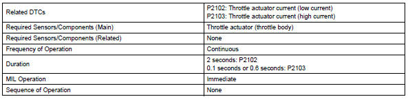
Typical enabling conditions
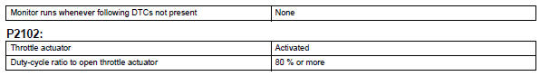
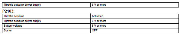
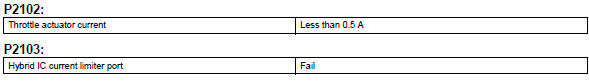
Typical malfunction thresholds
Fail-safe
When either of these dtcs, or other dtcs relating to etcs (electronic throttle control system) malfunctions, are set, the ecm enters fail-safe mode. During fail-safe mode, the ecm cuts the current to the throttle actuator off, and the throttle valve is returned to a 6° throttle angle by the return spring. The ecm then adjusts the engine output by controlling the fuel injection (intermittent fuel-cut) and ignition timing, in accordance with the accelerator pedal opening angle, to allow the vehicle to continue at a minimal speed. If the accelerator pedal is depressed firmly and gently, the vehicle can be driven slowly.
Fail-safe mode continues until a pass condition is detected, and the ignition switch is then turned off.
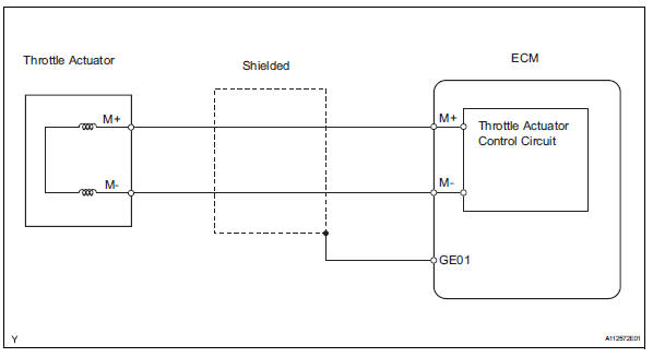
Wiring diagram
Inspection procedure
Hint
- Read freeze frame data using the intelligent tester. Freeze frame data records the engine condition when malfunctions are detected. When troubleshooting, freeze frame data can help determine if the vehicle was moving or stationary, if the engine was warmed up or not, if the air-fuel ratio was lean or rich, and other data from the time the malfunction occurred.
- The throttle actuator current (throttle mot) and the throttle actuator duty ratio (throtl opn duty / throtl cls duty) can be read using the intelligent tester. However, the ecm shuts off the throttle actuator current when the etcs malfunctions.
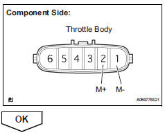
- Inspect throttle body (resistance of throttle actuator)
- Disconnect the b3 throttle body connector.
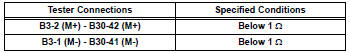
- Measure the resistance of the throttle actuator.
Standard resistance 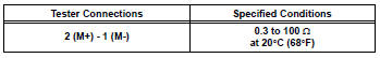
- Reconnect the throttle body connector.

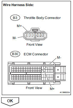
- Check harness and connector (throttle actuator - ecm)
- Disconnect the b3 throttle body connector.
- Disconnect the b30 ecm connector.
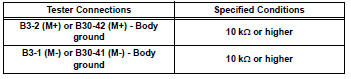
- Measure the resistance.
Standard resistance (check for open)
Standard resistance (check for short)
- Reconnect the throttle body connector.
- Reconnect the ecm connector.
- Inspect throttle body assembly
- Check for foreign objects between the throttle valve and the housing.
Ok: no foreign objects between throttle valve and housing.

- Inspect throttle valve
- Check if the throttle valve opens and closes smoothly.
Ok: throttle valve opens and closes smoothly.

 Deterioration of battery
Description
The ecm determines the battery power according to the voltage of the batt
terminal while the engine is
running (not cranking).
Inspection procedure
Inspect battery
Inspe ...
 Throttle actuator control system
Description
The throttle actuator is operated by the ecm, and opens and closes the
throttle valve using gears. The
opening angle of the throttle valve is detected by the throttle position (tp) ...
Other materials:
Disassembly
Hint:
Use the same procedures for the rh side and lh side.
The procedures listed below are for the lh side.
Remove no. 1 Rear seat reclining cover lh
Remove the 2 screws.
Using a screwdriver, detach the 5 claws and remove
the cover.
Hint:
Tape the screwdriver tip before ...
Headlight assembly
Components
Removal
Hint:
Use the same procedures for the rh and lh sides.
The procedures listed below are for the lh side.
Disconnect cable from negative battery
terminal
Remove front fender liner lh (see page et-4)
Remove front fender liner rh (see page et-4)
Remove ra ...
