Toyota RAV4 (XA40) 2013-2018 Service Manual: Trouble in passenger airbag on / off indicator
Description
The occupant classification system detects the front passenger seat condition and then indicates whether the front passenger airbag is activated or not through the passenger airbag on / off indicator illumination.
The passenger airbag on / off indicator illumination changes depending on the front passenger seat condition as shown in the table below.

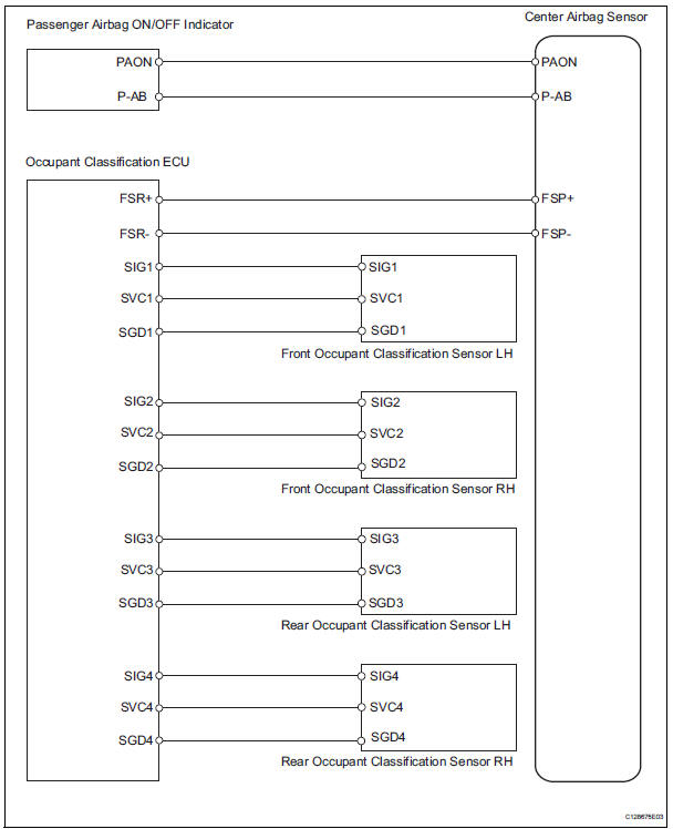
Wiring diagram
Inspection procedure
- Check srs warning light
- Turn the ignition switch on, and check the srs warning light condition.
Ok: the srs warning light does not come on.


- Check passenger airbag on/off indicator condition
- Turn the ignition switch on.
- Check if the passenger airbag on / off indicator correctly indicates the front passenger seat condition.
Ok 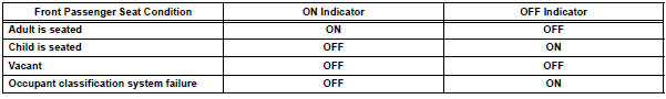


- Perform zero point calibration
- Turn the ignition switch off.
- Connect the intelligent tester (with can vim) to the dlc3.
- Turn the ignition switch on.
- Using the intelligent tester, perform the zero point calibration (see page rs-241).
Ok: completed is displayed.


- Perform sensitivity check
- Using the intelligent tester, perform the sensitivity check (see page rs-241).
Standard value: 27 to 33 kg (59.52 To 72.75 Lb)


End
- Retighten front seat assembly rh bolt
- Turn the ignition switch off.
- Loosen the 4 installation bolts of the front seat rh.
- Tighten the 4 installation bolts of the front seat rh to the specified torque (see page se-22).
Torque: 37 n*m{ 377 kgf*cm , 27 ft.*Lbf }


- Perform zero point calibration
- Connect the intelligent tester (with can vim) to the dlc3.
- Turn the ignition switch on.
- Using the intelligent tester, perform the zero point calibration (see page rs-241).
Ok: completed is displayed.


- Perform sensitivity check
- Using the intelligent tester, perform the sensitivity check (see page rs-241).
Standard value: 27 to 33 kg (59.52 To 72.75 Lb)


- Check connector
- Turn the ignition switch off.
- Disconnect the cable from the negative (-) battery terminal, and wait for at least 90 seconds.
- Check that the connectors are properly connected to the occupant classification ecu and the 4 occupant classification sensors.
Ok: the connectors are connected.
- Disconnect the connectors from the occupant classification ecu and the 4 occupant classification sensors.
- Check that the connectors are not damaged or deformed.
Ok: the connectors are normal.

- Check for dtc
- Connect the connectors to the occupant classification ecu and the 4 occupant classification sensors.
- Connect the cable to the negative (-) battery terminal, and wait for at least 2 seconds.
- Turn the ignition switch on, and wait for at least 60 seconds.
- Turn the ignition switch off.
- Clear the dtcs (see page rs-249).
- Turn the ignition switch on, and wait for at least 60 seconds.
- Check the dtcs (see page rs-249).
Ok: dtc is not output.

- Replace occupant classification ecu
- Turn the ignition switch off.
- Disconnect the cable from the negative (-) battery terminal, and wait for at least 90 seconds.
- Replace the occupant classification ecu (see page rs- 392).
Hint:
Perform the inspection using parts from a normal vehicle if possible.

- Perform zero point calibration
- Connect the cable to the negative (-) battery terminal, and wait for at least 2 seconds.
- Connect the intelligent tester (with can vim) to the dlc3.
- Turn the ignition switch on.
- Using the intelligent tester, perform the zero point calibration (see page rs-241).
Ok: completed is displayed.

- Perform sensitivity check
- Using the intelligent tester, perform the sensitivity check (see page rs-241).
Standard value: 27 to 33 kg (59.52 To 72.75 Lb)

End
 Sleep operation failure of occupant classification ecu
Description
During sleep mode, the occupant classification ecu reads the condition of
each sensor while the ignition
switch is off.
In this mode, if the occupant classification ecu detects ...
 Steering pad
Components
...
Other materials:
Components
Fuse boxes
Engine oil filler cap
Engine oil level dipstick
Battery
Brake fluid reservoir
Radiator
Electric cooling fan
Condenser
Washer fluid tank
Engine coolant reservoir
Checking the engine oil
With the engine at operating
temperature and turned off,
check the oil level on the di ...
Headlight relay
On-vehicle inspection
Remove headlight relay
Remove the headlight relay from the engine room
no. 2 Relay block.
Measure the resistance of the relay.
Standard resistance
If result is not as specified, replace the relay. ...
Removal
Hint:
Use the same procedures for the rh side and lh side.
The procedures listed below are for the lh side.
Caution:
Be sure to read the precautionary notices concerning the
srs airbag system before servicing it (see page rs-1).
Disconnect cable from negative battery terminal
Cauti ...
