Toyota RAV4 (XA40) 2013-2018 Service Manual: Front fog light circuit
Description
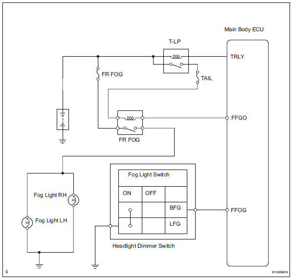
The main body ecu controls the front fog light relay (marking: fr fog) when a signal is received from the headlight dimmer switch.
Wiring diagram
Inspection procedure
- Perform active test by intelligent tester
- Connect the intelligent tester (with can vim) to the dlc3.
- Turn the ignition switch to the on position and press the intelligent tester main switch on.
- Select the item below in the active test and then check the relay operation.

Ok: front fog light comes on.

- Check taillight
- Check that the taillight comes on when the light control switch is on (tail).
Ok: taillight comes on.

- Inspect fuse (fr fog)
- Remove the fr fog fuse from the instrument panel junction block.
- Measure the resistance of the fuses.
Standard resistance:
below 1 


- Inspect fog light bulb
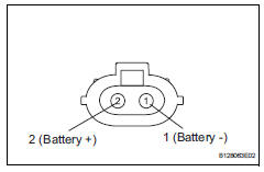
- Remove the fog light bulb.
- Connect the positive (+) lead from the battery to terminal 2 and the negative (-) lead to terminal 1, then check that the bulb illuminates.
Ok: bulb illuminates.


- Inspect front fog light relay (marking: fr fog)
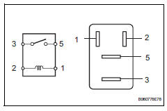
- Remove the front fog light relay from the no. 6 Relay block.
- Measure the resistance of the relay.
Standard resistance 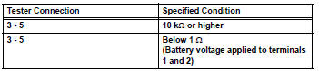

- Check wire harness (battery - main body ecu)
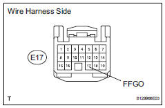
- Disconnect the e17 ecu connector.
- Measure the voltage of the wire harness side connector.
Standard voltage 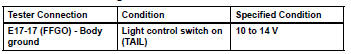

- Check wire harness (front fog light relay - battery)
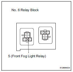
- Remove the front fog light relay from the no. 6 Relay block.
- Measure the voltage of the relay block.
Standard voltage 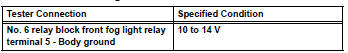

- Check wire harness (front fog light relay - front fog light and body ground)
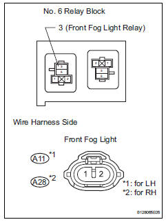
- Remove the front fog light relay from the no. 6 Relay block.
- Disconnect the a11 and a28 front fog light connectors.
- Measure the resistance of the wire harness side connectors.
Standard resistance 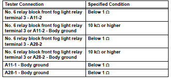

Replace instrument panel junction block (main body ecu)
- Check wire harness (dimmer switch - main body ecu and body ground)
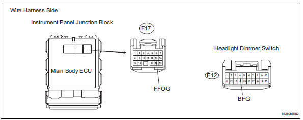
- Disconnect the e12 headlight dimmer switch connector.
- Disconnect the e17 main body ecu connector.
- Measure the resistance of the wire harness side connectors.
Standard resistance 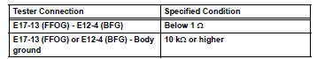

- Inspect fog light switch
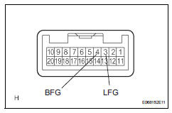
- Remove the headlight dimmer switch.
- Measure the resistance of the switch.
Standard resistance 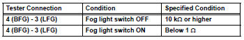

Repair or replace harness and connector (headlight dimmer switch - body ground)
 Headlight (hi-beam) circuit
Description
The body ecu controls the headlight relay, no. 2 Daytime running light relay
(marking: drl no. 2) And
no. 4 Daytime running light relay (marking: drl no. 4).
Wiring diagram
I ...
 Turn signal light circuit
Description
The turn signal flasher relay (marking: flsh) in the main body ecu turns on
when it receives signals
from the headlight dimmer switch integrated with the turn signal switch, causing
...
Other materials:
Front wiper motor and link
Components
Removal
Disconnect cable from negative battery
terminal
Caution:
Wait at least 90 seconds after disconnecting the
cable from the negative (-) battery terminal to
prevent airbag and seat belt pretensioner activation.
Remove front wiper arm head cap
Remove the 2 c ...
Compressor solenoid circuit (2006/01- )
Description
In this circuit, the compressor receives a refrigerant compression demand
signal from the air conditioning
amplifier. Based on this signal, the compressor changes the degree of
refrigerant compression.
Hint:
*: Compressor and pulley for 2az-fe, compressor and magnetic clutc ...
Seat heaters
Turns on the front left seat
heater (high)
Turns on the front left seat
heater (low)
Turns on the front right seat
heater (high)
Turns on the front right seat
heater (low)
The indicator light comes on.
The seat heaters can be used when
Vehicles without a smart key system
T ...
