Toyota RAV4 (XA40) 2013-2018 Service Manual: Headlight (hi-beam) circuit
Description
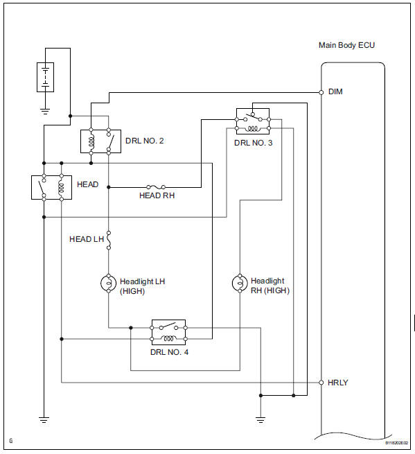
The body ecu controls the headlight relay, no. 2 Daytime running light relay (marking: drl no. 2) And no. 4 Daytime running light relay (marking: drl no. 4).
Wiring diagram
Inspection procedure
- Perform active test by intelligent tester
- Connect the intelligent tester (with can vim) to the dlc3.
- Turn the ignition switch to the on position and press the intelligent tester main switch on.
- Select the item below in the active test and then check the relay operation.
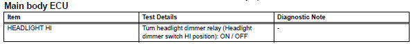
Ok: headlight (high) comes on.

- Check headlight (low)
- Check that the headlight (low) comes on when the light control switch is on (head).
Ok: headlight (low) comes on.

- Inspect fuse (head lh, head rh)
- Remove the head lh fuse and head rh fuse from the engine room no. 2 Relay block.
- Measure the resistance of the fuses.
Standard resistance:
below 1 

- Inspect daytime running light relay (marking: drl no. 2, Drl no. 3, Drl no. 4)
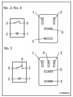
- Remove the no. 2 Relay, no. 3 Relay and no. 4 Relay from the engine room no. 2 Relay block.
- Measure the resistance of the relays.
Standard resistance:
No. 2, No. 4 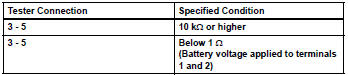
No. 3 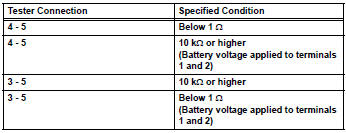

- Inspect headlight bulb (high)
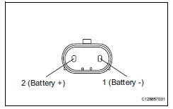
- Remove the headlight bulb (high).
- Connect the positive (+) lead from the battery to terminal 2 and the negative (-) lead to terminal 1, then check that the bulb illuminates.

- Check wire harness (main body ecu - battery)
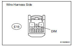
- Disconnect the e16 main body ecu connector.
- Measure the voltage of the wire harness side connector.
Standard voltage 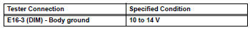

- Check wire harness (main body ecu)
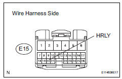
- Remove the headlight relay from the engine room no. 2 Relay block.
- Disconnect the e15 main body ecu connector.
- Measure the voltage of the wire harness side connector.
Standard voltage 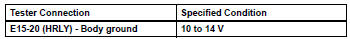

- Check wire harness (headlight relay - no. 3 Daytime running light relay and body ground)
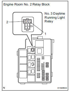
- Remove the no. 3 Daytime running light relay from the engine room no. 2 Relay block.
- Measure the voltage and resistance of the relay block.
Standard voltage 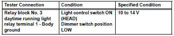
Standard resistance 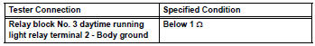

- Check wire harness (battery - no. 2 Daytime running light relay, bulb and body ground)
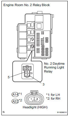
- Remove the no. 2 Daytime running light relay from the engine room no. 2 Relay block.
- Remove the a14 and a22 headlight bulb connectors.
- Measure the voltage and resistance of the relay block.
Standard voltage 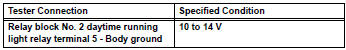
Standard resistance 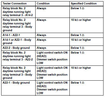

Replace instrument panel junction block (main body ecu)
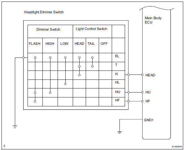
- Check wire harness (main body ecu - dimmer switch)
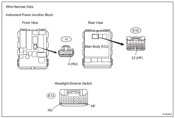
- Disconnect the e15 main body ecu connector.
- Disconnect the e12 headlight dimmer switch connector.
- Disconnect the ij instrument panel junction block connector.
- Measure the resistance of the wire harness side connectors.
Standard resistance 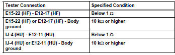

- Inspect headlight dimmer switch
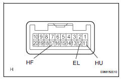
- Remove the headlight dimmer switch.
- Measure the resistance of the switch.
Standard resistance 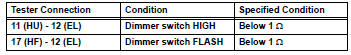

Repair or replace harness and connector (headlight dimmer switch - body ground)
 Drl relay circuit
Description
The main body ecu controls the daytime running light no. 2 Relay (marking:
drl no.2).
Wiring diagram
Inspection procedure
Inspect daytime running light relay (marking: drl no. ...
 Front fog light circuit
Description
The main body ecu controls the front fog light relay (marking: fr fog) when a
signal is received from
the headlight dimmer switch.
Wiring diagram
Inspection procedure
Perform ...
Other materials:
Snow mode switch (AWD
vehicles)
Snow mode can be selected
to suit the conditions when
driving on slippery road surfaces,
such as on snow.
System operation
â– Dynamic Torque Control
AWD vehicles
Press the snow mode switch.
When the switch is pressed, the
system switches to snow mode and
the snow mode indicator illuminates
on the ...
Occupant classification ecu malfunction
Description
Dtc b1795 is recorded when a malfunction is detected in the occupant
classification ecu.
Troubleshoot dtc b1771 first when dtc b1771 and b1795 are output simultaneously.
Wiring diagram
Inspection procedure
Check for dtc
Turn the ignition switch on, and wait ...
Console box
Lift the lid while pulling up the
lever to release the lock.
When using the console box lid as an armrest (vehicles with slide
function)
Slide the console box lid forward as
needed. Pull the lid forward by holding the
front of the lid.
Caution
Console box adjustment precaution
D ...
