Toyota RAV4 (XA40) 2013-2018 Service Manual: Drl relay circuit
Description
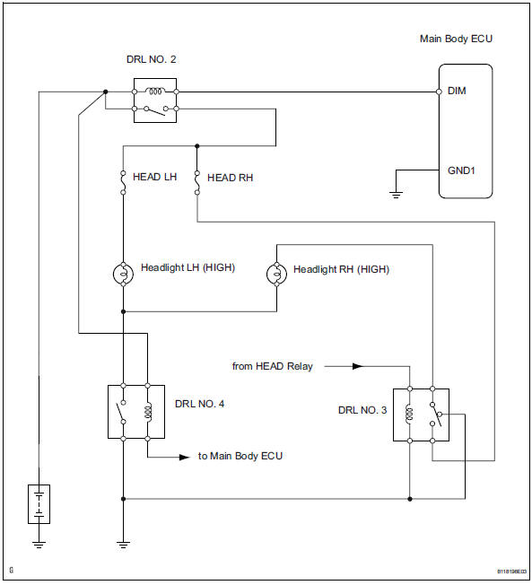
The main body ecu controls the daytime running light no. 2 Relay (marking: drl no.2).
Wiring diagram
Inspection procedure
- Inspect daytime running light relay (marking: drl no. 2, Drl no. 3, Drl no. 4)
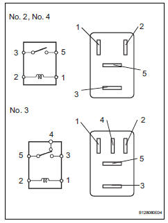
- Remove the no. 2 Relay, no. 3 Relay and no. 4 Relay from the engine room no. 2 Relay block.
- Measure the resistance of the relays.
Standard resistance:
No. 2, No. 4 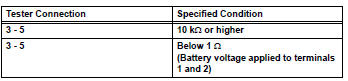
No. 3 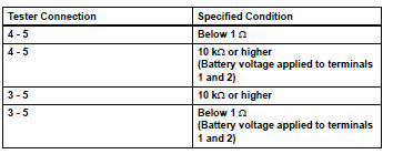

- Inspect fuse (head lh)
- Remove the head lh fuse from the engine room no. 2 Relay block.
- Measure the resistance of the fuse.
Standard resistance:
below 1 

- Inspect headlight bulb (high)
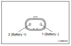
- Remove the headlight bulb (high).
- Connect the positive (+) lead from the battery to terminal 2 and the negative (-) lead to terminal 1, then check that the bulb illuminates.

- Check wire harness (battery - no. 2 Daytime running light relay)
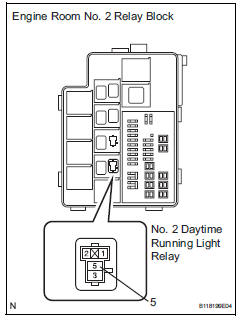
- Remove the no. 2 Daytime running light relay from the engine room no. 2 Relay block.
- Measure the voltage of the relay block.
Standard voltage 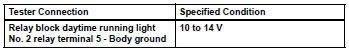

- Check wire harness (no. 2 Daytime running light relay - headlight bulb and body ground)
- Remove the no. 2 Daytime running light relay from the engine room no. 2 Relay block.
- Disconnect the a14 and a22 headlight (high) connectors.
- Measure the resistance of the wire harness side connectors and relay block.
Standard resistance 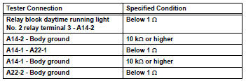

- Check wire harness (main body ecu - battery)
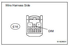
- Disconnect the e16 main body ecu connector.
- Measure the voltage of the wire harness side connector.
Standard voltage 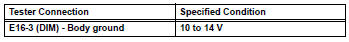

Replace instrument panel junction block (main body ecu)
 Headlight relay circuit
Description
When the light control switch, located on the headlight dimmer switch, is
turned to the head position, the
head relay illuminates the headlights.
Wiring diagram
Inspection proced ...
 Headlight (hi-beam) circuit
Description
The body ecu controls the headlight relay, no. 2 Daytime running light relay
(marking: drl no. 2) And
no. 4 Daytime running light relay (marking: drl no. 4).
Wiring diagram
I ...
Other materials:
Dtc check / clear
Check dtc
Dtcs which are stored in the ecm can be displayed
with the intelligent tester.
The intelligent tester can display pending dtcs and
current dtcs. Some dtcs are not stored unless a
malfunction is detected in consecutive driving
cycles. When a malfunction is detected ...
Vc output circuit
Description
The ecm constantly generates 5 v power from the battery voltages supplied to
the +b (batt) terminal to
operate the microprocessor. The ecm also provides this power to the sensors
through the vc output
circuit.
When the vc circuit is short-circuited, the microprocessor in the ...
Diagnosis system
Description
Power door lock control system data can be read in the
data link connector 3 (dlc3) of the vehicle. When the
system seems to be malfunctioning, use the intelligent
tester to check for malfunctions and perform repairs.
Check dlc3
The ecu uses iso 15765-4 for communi ...
