Toyota RAV4 (XA40) 2013-2018 Service Manual: Ig power source circuit
Description
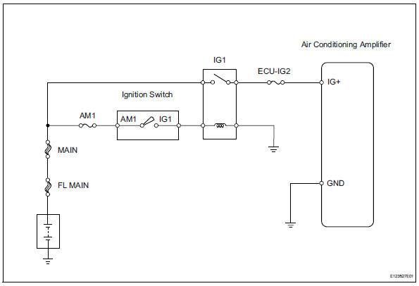
This is the main power source supplied to the air conditioning amplifier when the ignition switch is on.
This power source is used for operating components, such as the air conditioning amplifier and servo motors.
Wiring diagram
Inspection procedure
- Inspect fuse (ecu-ig2)
- Remove the ecu-ig2 fuse from the instrument panel junction block.
- Measure the resistance of the fuse.
Standard resistance:
below 1 


- Check wire harness (air conditioning amplifier - battery)
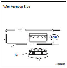
- Disconnect the e36 amplifier connector.
- Measure the voltage of the wire harness side connector.
Standard voltage 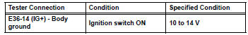

- Check wire harness (air conditioning amplifier - body ground)
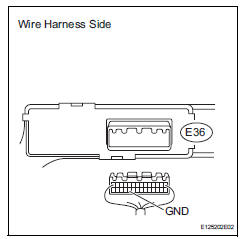
- Disconnect the e36 amplifier connector.
- Measure the resistance of the wire harness side connector.
Standard resistance 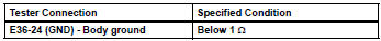

Proceed to next circuit inspection shown in problem symptoms table
 Compressor circuit
Description
When the a/c switch is turned on, the magnetic clutch on signal is sent from
the air conditioning
amplifier. Then the mg clt relay turns on to operate the magnetic clutch.
Wiring diag ...
 Refrigerant
...
Other materials:
Pressure sensor circuit
Description
This dtc is output when the refrigerant pressure is either extremely low
(0.19 Mpa [2.0 Kgf/cm2, 28 psi]
or less) or extremely high (3.14 Mpa [32.0 Kgf/cm2, 455 psi] or more). The air
conditioning pressure
sensor, which is installed on the pipe of the high pressure side, detec ...
Basic audio operations
Basic audio operations and functions common to each mode are
explained in this section.
Operating the audio system
Press this knob to turn the
audio system on and off, and
turn it to adjust the volume.
Press this button to eject a disc
Insert a disc into the disc slot
Press to pa ...
Front occupant classification sensor rh circuit malfunction
Description
The front occupant classification sensor rh circuit consists of the occupant
classification ecu and the
front occupant classification sensor rh.
Dtc b1781 is recorded when a malfunction is detected in the front occupant
classification sensor rh
circuit.
Wiring diagram
...
