Toyota RAV4 (XA40) 2013-2018 Service Manual: Compressor circuit
Description
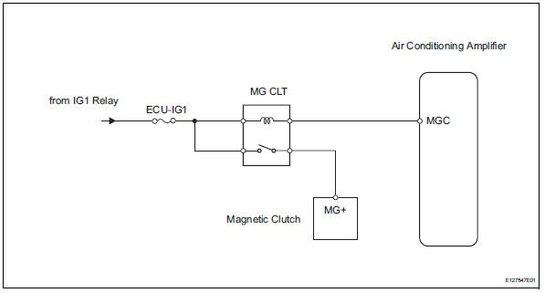
When the a/c switch is turned on, the magnetic clutch on signal is sent from the air conditioning amplifier. Then the mg clt relay turns on to operate the magnetic clutch.
Wiring diagram
Inspection procedure
Inspection procedure
- Perform active test by intelligent tester (a/c mag clutch)
- Connect the intelligent tester (with can vim) to the dlc3.
- Turn the ignition switch on and turn the intelligent tester main switch on.
- Select the item below in the active test and then check that the compressor magnetic relay operates.


- Inspect fuse (ecu-ig1)
- Remove the ecu-ig1 fuse from the instrument panel junction block.
- Measure the resistance of the fuse.
Standard resistance:
below 1

- Inspect magnetic clutch relay (marking: mg clt)
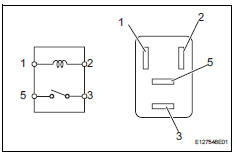
- Remove the magnetic clutch relay from the engine room no. 1 Relay block.
- Measure the resistance of the relay.
Standard resistance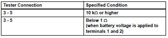

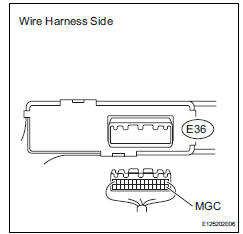
- Check wire harness (air conditioning amplifier - battery)
- Disconnect the e36 amplifier connector.
- Measure the voltage of the wire harness side connector.
Standard voltage 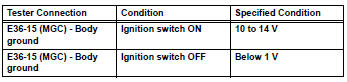

- Check air conditioning amplifier (mgc voltage)
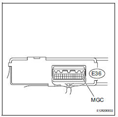
- Remove the air conditioning amplifier with its connectors still connected.
- Measure the voltage of the connector.
Standard voltage 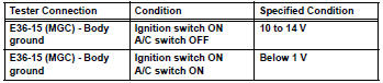


- Check magnetic clutch
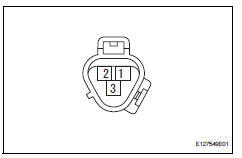
- Disconnect the b47 magnetic clutch connector.
- Connect the battery's positive (+) lead to terminal 3 of the magnetic clutch and the negative (-) lead to the body ground.
Ok: magnetic clutch is engaged.


Repair or replace wire harness (magnetic clutch - ecu-ig1)
 Blower motor circuit
Description
When the heater control (blower switch) is set to position 1 or higher, the
contact of the htr relay is
closed, current flows to the blower motor, and the blower motor operates. The
...
 Ig power source circuit
Description
This is the main power source supplied to the air conditioning amplifier when
the ignition switch is on.
This power source is used for operating components, such as the air condition ...
Other materials:
Displaying a bluetooth®
device details
You can confirm and change the registered device details.
Bluetooth® device registration status
Display the “bluetooth* setup” screen.
*: Bluetooth is a registered trademark of bluetooth sig, inc.
Select the device.
Select “device info”.
Following screen is displayed:
...
Lda
(lane departure alert)
Summary of function
While driving on a road that has lane markers, this system recognizes
the lane markers using a camera as a sensor to alert the driver when
the vehicle deviates from its lane.
If the system judges that the vehicle may deviate from its lane, it alerts
the driver using beepin ...
Air fuel ratio sensor
Components
On-vehicle inspection
Check air fuel ratio compensation system
Connect the intelligent tester to the dlc3.
Turn the ignition switch on.
Select the following menu items: data list / a/fs b1
s1 and o2s b1 s2.
Warm up the a/f sensor with the engine speed at
2,500 ...
