Toyota RAV4 (XA40) 2013-2018 Service Manual: Blower motor circuit
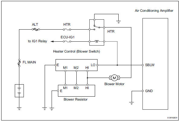
Description
When the heater control (blower switch) is set to position 1 or higher, the contact of the htr relay is closed, current flows to the blower motor, and the blower motor operates. The blower motor speed can be changed by exchanging the ground and the blower resistor circuit with the heater control (blower switch).
Wiring diagram
Inspection procedure
- Inspect fuse (htr)
- Remove the htr fuse from the engine room no. 2 Relay block.
- Measure the resistance of the fuse.
Standard resistance:
below 1

- Inspect heater relay (marking: htr)
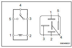
- Remove the heater relay from the instrument panel junction block.
- Measure the resistance of the relay.
Standard resistance 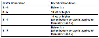

- Inspect blower motor
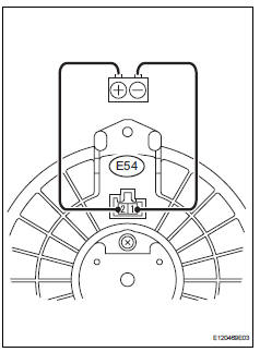
- Disconnect the e54 motor connector.
- Connect the positive (+) lead from the battery to terminal 2 and the negative (-) lead to terminal 1, then check that the blower motor operates smoothly.
Ok: the blower motor operates smoothly.
- Measure the current.
Standard current 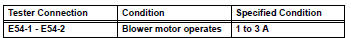

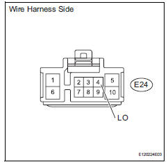
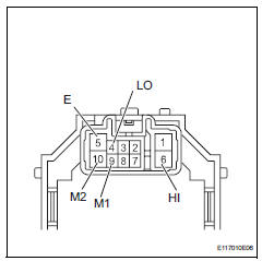
- Check wire harness (heater control (blower switch) - battery)
- Disconnect the e24 heater control connector.
- Measure the voltage of the wire harness side connector.
Standard voltage 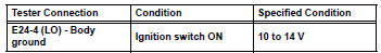

- Inspect heater control (blower switch)
- Remove the heater control.
- Measure the resistance of the switch.
Standard resistance 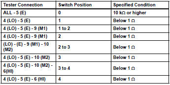

- Inspect blower resistor
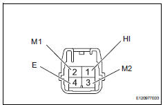
- Remove the blower resistor.
- Measure the resistance of the resistor.
Standard resistance 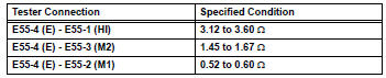

- Check wire harness (heater control (blower switch) - blower resistor)
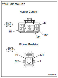
- Disconnect the e24 heater control connector.
- Disconnect the e55 blower resistor connector.
- Measure the resistance of the wire harness side connectors.
Standard resistance 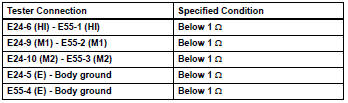

- Check wire harness (blower resistor - blower motor)
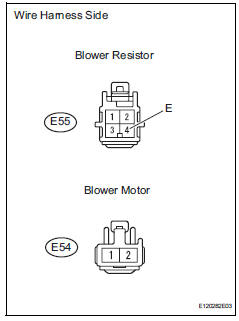
- Disconnect the e55 blower resistor connector.
- Disconnect the e54 motor connector
- Measure the resistance of the wire harness side connectors.
Standard resistance 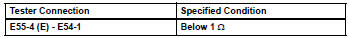

- Check wire harness (blower motor - body ground)
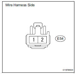
- Disconnect the e54 motor connector.
- Measure the resistance of the wire harness side connector.
Standard resistance 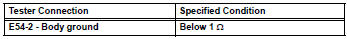
- Measure the voltage of the wire harness side connector.
Standard voltage 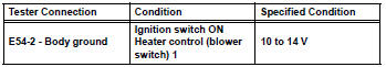

- Check wire harness (air conditioning amplifier - battery)
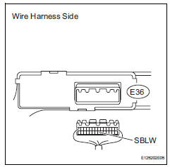
- Disconnect the e36 amplifier connector.
- Measure the voltage of the wire harness side connector.
Standard voltage 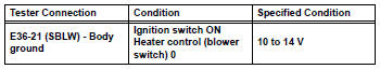

- Check wire harness (air conditioning amplifier - body ground)
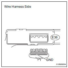
- Disconnect the e36 amplifier connector.
- Measure the resistance of the wire harness side connector.
Standard resistance 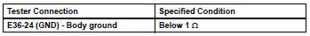

Proceed to next circuit inspection shown in problem symptoms table
 Multiplex communication circuit
Description
The air conditioning amplifier communicates data with the ecm and combination
meter through the can
communication system.
Wiring diagram
Inspection procedure
Check dt ...
 Compressor circuit
Description
When the a/c switch is turned on, the magnetic clutch on signal is sent from
the air conditioning
amplifier. Then the mg clt relay turns on to operate the magnetic clutch.
Wiring diag ...
Other materials:
Curtain shield airbag assembly
Components
On-vehicle inspection
Check curtain shield airbag assembly (vehicle not involved in
collision)
Perform a diagnostic system check (see page rs-
49).
With the curtain shield airbag assembly installed on
the vehicle, perform a visual check. If any of the
defects ...
On-vehicle inspection
Check driver side seat belt warning light
Turn the ignition switch on.
When the driver side seat belt is not fastened, check
that the combination meter's driver side seat belt
warning light starts blinking.
When the seat belt is fastened, check that the
combination meter's driver ...
Warning lights and indicators
The warning lights and indicators on the instrument cluster and
center panel inform the driver of the status of the vehicle’s various
systems.
For the purpose of explanation, the following illustration displays
all warning lights and indicators illuminated.
Instrument cluster
Some indi ...
