Toyota RAV4 (XA40) 2013-2018 Service Manual: Only rear door rh lock / unlock functions do not operate
Description
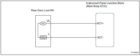
The main body ecu receives lock / unlock switch signals and activates the door lock motor accordingly.
Wiring diagram
Inspection procedure
- Inspect rear door with motor lock assembly rh
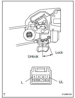
- Apply the battery voltage to the door lock motor and check the operation of the door lock motor.
Ok 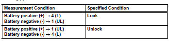

- Check wire harness (door lock - ecu)
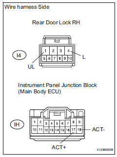
- Disconnect the i4 door lock connector.
- Disconnect the ih junction block connector.
- Measure the resistance of the wire harness side connectors.
Standard resistance 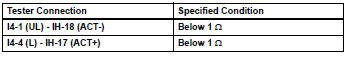

Replace instrument panel junction block (main body ecu)
 Only rear door lh lock / unlock functions do not operate
Description
The main body ecu receives lock / unlock switch signals and activates the
door lock motor accordingly.
Wiring diagram
Inspection procedure
Inspect rear door with motor lock as ...
 Only back door lock / unlock functions do not operate
Description
The main body ecu receives lock / unlock switch signals and activates the
door lock motor accordingly.
Wiring diagram
Inspection procedure
Inspect back door with motor lock as ...
Other materials:
Removal
Table of bolt, screw and nut
Hint:
All bolts, screws and nuts relevant to installing and
removing the instrument panel are shown along with
their alphabet codes in the table below.
Disconnect cable from negative battery
terminal
Caution:
Wait at least 90 seconds after disconne ...
Wireless charger (if
equipped)
A portable device can be
charged by just placing Qi standard
wireless charge compatible
portable devices according to
the Wireless Power Consortium,
such as smartphones and
mobile batteries, etc., on the
charge area.
This function cannot be used
with portable devices that are
larger than the chargi ...
Rear seats
Adjustment procedure
Pull up the lever. Then lean back to the desired angle and release the
lever.
When a person sits in the rear center position, align all seatbacks at the
same angle.
Folding down the rear seatbacks
Before folding down the rear seatbacks
Stow the rear center seat bel ...
