Toyota RAV4 (XA40) 2013-2018 Service Manual: Only back door lock / unlock functions do not operate
Description
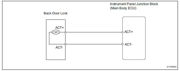
The main body ecu receives lock / unlock switch signals and activates the door lock motor accordingly.
Wiring diagram
Inspection procedure
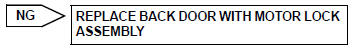
- Inspect back door with motor lock assembly
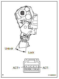
- Apply the battery voltage to the door lock motor and check the operation of the door lock motor.
Ok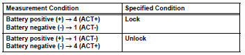

- Check wire harness (door lock - ecu)
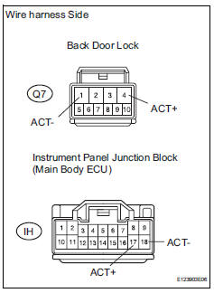
- Disconnect the q7 door lock connector.
- Disconnect the ih junction block connector.
- Measure the resistance of the wire harness side connectors.
Standard resistance 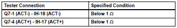

Replace instrument panel junction block (main body ecu)
 Only rear door rh lock / unlock functions do not operate
Description
The main body ecu receives lock / unlock switch signals and activates the
door lock motor accordingly.
Wiring diagram
Inspection procedure
Inspect rear door with motor lock as ...
 Key lock-in prevention function does not work properly
Description
When the key is in the ignition key cylinder or the door courtesy light on
signal is output to the main body
ecu, performing the door lock operation with the lock switch does not lock ...
Other materials:
If your vehicle has to
be stopped in an
emergency
Only in an emergency, such as if it becomes impossible to stop
the vehicle in the normal way, stop the vehicle using the following
procedure:
Steadily step on the brake pedal with both feet and firmly depress it.
Do not pump the brake pedal repeatedly as this will increase the effort
req ...
Installation
Notice:
Do not heat the vehicle body, emblem and name plate
excessively.
Hint:
When installing the emblem and name plate, heat the vehicle
body, emblem and name plate using a heat light.
Standard heating temperature
Install no. 4 Back door name plate (for 4wd)
Clean the vehicle body ...
Vehicle load limits
Vehicle load limits include total load capacity, seating capacity,
twr (trailer weight rating) and cargo capacity.
Total load capacity (vehicle capacity weight)
Total load capacity means the combined weight of occupants, cargo
and luggage.
Seating capacity: 5 occupants (front 2, rear 3)
Seatin ...
