Toyota RAV4 (XA40) 2013-2018 Service Manual: Key lock-in prevention function does not work properly
Description
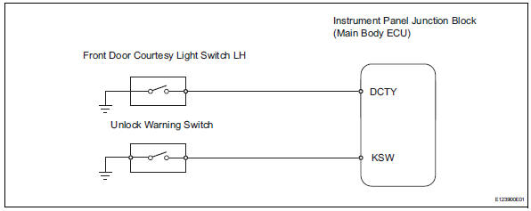
When the key is in the ignition key cylinder or the door courtesy light on signal is output to the main body ecu, performing the door lock operation with the lock switch does not lock the door.
Wiring diagram
Inspection procedure
- Read value of intelligent tester (unlock warning switch)
- Use the data list to check if the unlock warning switch is functioning properly.
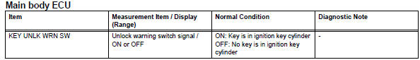
Ok: when the switch is operating, the intelligent tester should display as shown in the table.

- Read value of intelligent tester (driver side door courtesy light switch)
- Use the data list to check if the door courtesy light switch is functioning properly.
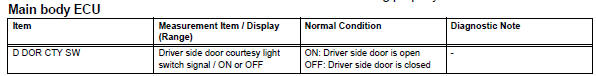
Ok: when the switch is operating, the intelligent tester should display as shown in the table.

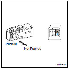
- Inspect front door courtesy light switch assembly lh
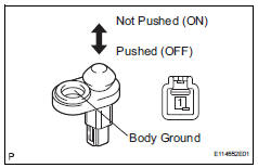
- Remove the front door courtesy light switch.
- Measure the resistance of the switch.
Standard resistance 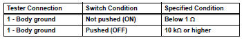

- Check wire harness (ecu - switch)
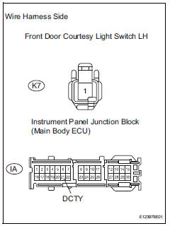
- Disconnect the k7 switch connector.
- Disconnect the ia junction block connector.
- Measure the resistance of the wire harness side connectors.
Standard resistance 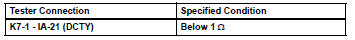

Replace instrument panel junction block (main body ecu)
- Inspect unlock warning switch assembly
- Remove the unlock warning switch.
- Measure the resistance of the switch.
Standard resistance 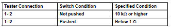

- Check wire harness (switch - ecu)
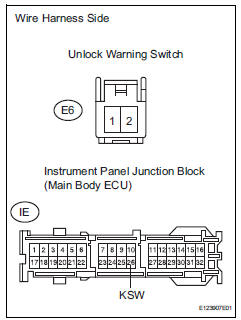
- Disconnect the e6 switch connector.
- Disconnect the ie junction block connector.
- Measure the resistance of the wire harness side connectors.
Standard resistance 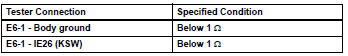

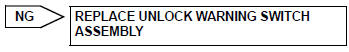
Replace instrument panel junction block (main body ecu)
 Only back door lock / unlock functions do not operate
Description
The main body ecu receives lock / unlock switch signals and activates the
door lock motor accordingly.
Wiring diagram
Inspection procedure
Inspect back door with motor lock as ...
 Key reminder warning system
Parts location
System diagram
...
Other materials:
Setup menu
You can adjust the audio system to your desired settings.
Display “setup” screen
Press the “setup” button to display the “setup” screen.
Select to adjust the settings for
operation sounds, screen animation,
etc.
Select to display the voice settings
screen.
Select to adjus ...
Fuel pump shut off
system
To minimize the risk of fuel leakage when the engine stalls or
when an airbag inflates upon collision, the fuel pump shut off
system stops the supply of fuel to the engine.
Follow the procedure below to restart the engine after the system is
activated.
Vehicles without a smart key system
Tu ...
Installation
Caution:
Be sure to read the precautionary notices concerning the
srs airbag system before servicing it (see page rs-1).
Install steering pad assembly
Support the steering pad with one hand as shown in
the illustration.
Connect the 2 airbag connectors.
Notice:
When handling t ...
