Toyota RAV4 (XA40) 2013-2018 Service Manual: Only rear door lh lock / unlock functions do not operate
Description
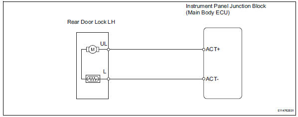
The main body ecu receives lock / unlock switch signals and activates the door lock motor accordingly.
Wiring diagram
Inspection procedure
- Inspect rear door with motor lock assembly lh
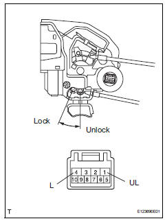
- Apply the battery voltage to the door lock motor and check the operation of the door lock motor.
Ok 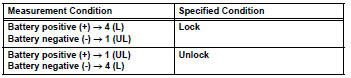

- Check wire harness (door lock - ecu)
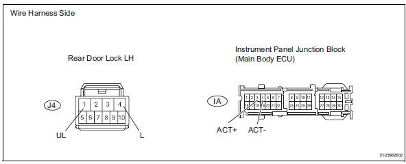
- Disconnect the j4 door lock connector.
- Disconnect the ia junction block connector.
- Measure the resistance of the wire harness side connectors.
Standard resistance 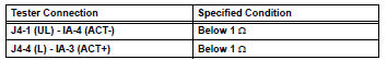

Replace instrument panel junction block (main body ecu)
 Only passenger door lock / unlock functions do not operate
Description
The main body ecu receives lock / unlock switch signals and activates the
door lock motor accordingly.
Wiring diagram
Inspection procedure
Read value of intelligent tester (lo ...
 Only rear door rh lock / unlock functions do not operate
Description
The main body ecu receives lock / unlock switch signals and activates the
door lock motor accordingly.
Wiring diagram
Inspection procedure
Inspect rear door with motor lock as ...
Other materials:
Hill-start assist control
When the engine is stopped by
the Stop & Start system when
the vehicle is on an incline,
when the brake pedal is
released, brake force is temporarily
maintained to prevent the
vehicle from rolling backwards
before the engine is restarted
and drive force is generated.
When drive force is generat ...
The rear cross traffic alert function detection areas
The areas that vehicles can be detected in are outlined below.
To give the driver a more consistent time to react, the buzzer can alert
for faster vehicles from farther away.
Example:
The rear cross traffic alert function is operational when
The bsm main switch is set to on.
The shift ...
Installation (2006/01- )
Install front drive shaft assembly lh
Coat the spline of the inboard joint shaft with gear
oil.
Align the shaft splines and tap in the drive shaft with
a brass bar and hammer.
Notice:
Set the snap ring with the opening side facing
downwards.
Be careful not to damage the ...
