Toyota RAV4 (XA40) 2013-2018 Service Manual: Lower instrument panel
Precaution
- Precaution for vehicle with srs airbag and seat belt pretensioner
- Some operations in this section may affect the srs airbags and seat belt pretensioner. Prior to performing the corresponding operations, read the srs airbag notice (see page rs-1).
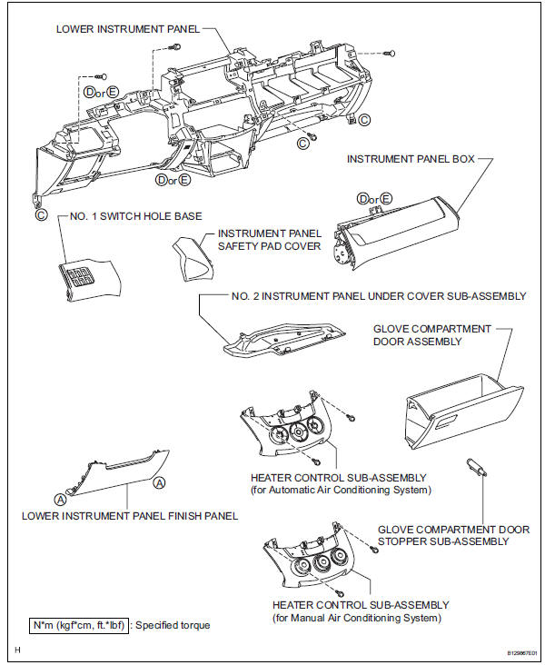
Components
Removal
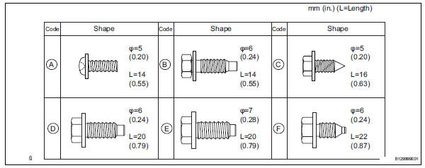
- Table of bolt, screw and nut
Hint:
All bolts, screws and nuts relevant to installing and removing the instrument panel are shown along with their alphabet codes in the table below.
- Disconnect cable from negative battery terminal
Caution:
Wait at least 90 seconds after disconnecting the cable from the negative (-) battery terminal to prevent airbag and seat belt pretensioner activation.
- Remove instrument panel sub-assembly
- Remove the instrument panel (see page ip-4).
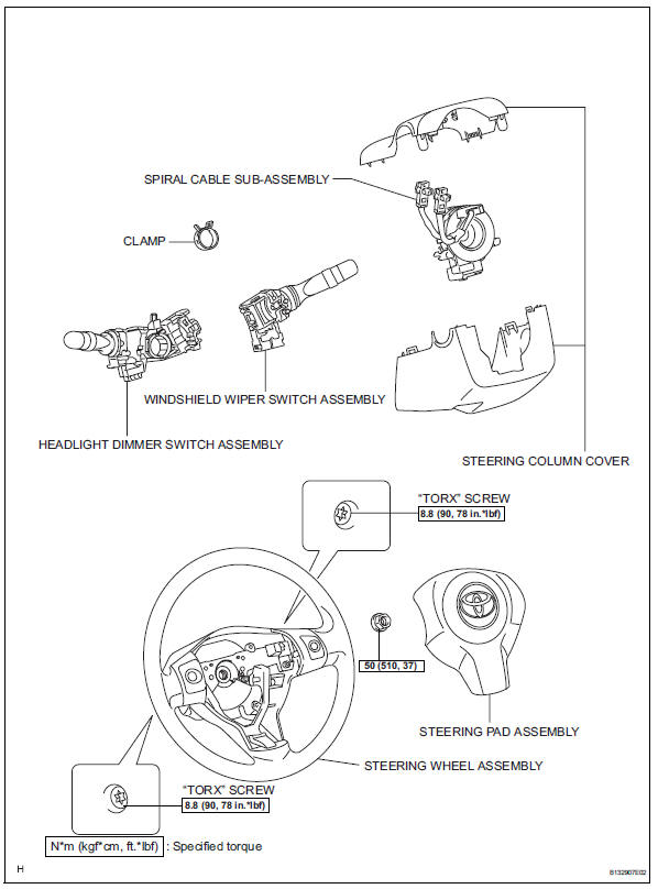
- Remove steering pad assembly (see page rs- 336)
- Remove steering wheel assembly (see page sr-12)
- Remove steering column cover (see page sr-12)
- Remove spiral cable sub-assembly (see page rs-346)
- Remove headlight dimmer switch assembly
- Remove windshield wiper switch assembly
- Remove heater control sub-assembly (for automatic air conditioning system) (see page ac- 241)
- Remove heater control sub-assembly (for manual air conditioning system) (see page ac-243)
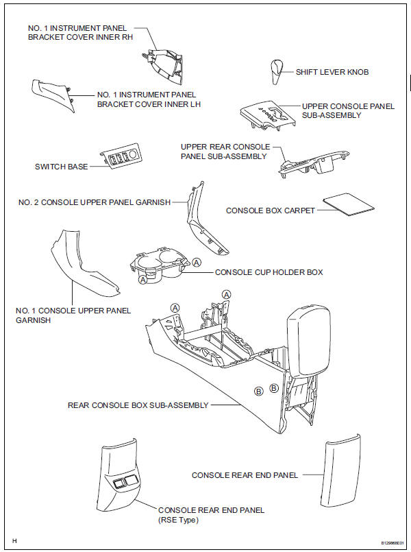
- Remove no. 1 Console upper panel garnish
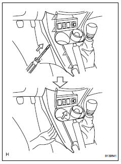
- Using a screwdriver, detach the 4 clips and upper panel garnish.
Hint:
Tape the screwdriver tip before use.
- Remove no. 2 Console upper panel garnish
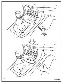
- Using a screwdriver, detach the 4 clips and upper panel garnish.
Hint:
Tape the screwdriver tip before use.
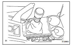
- Remove upper console panel sub-assembly
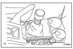
- Remove the shift lever knob.
- Using a screwdriver, detach the 2 clips, 4 claws and remove the upper console panel then disconnect the connector.
Hint:
Tape the screwdriver tip before use.
- Remove switch base
- Detach the 2 clips and 2 claws.
- Disconnect the connectors and remove the switch base.
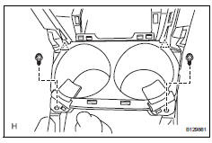
- Remove console cup holder box
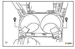
- Remove the 2 screws.
- Detach the 2 clips and remove the cup holder box.
- Remove upper rear console panel subassembly
- Using a screwdriver, detach the 4 claws and 2 clips.
Hint:
Tape the screwdriver tip before use.
- Disconnect the connector and remove the upper rear console panel.
- Remove console rear end panel
- Using a screwdriver, detach the 6 claws and remove the console rear end panel.
Hint:
Tape the screwdriver tip before use.
- Remove console rear end panel (rse type)
- Using a screwdriver, detach the 4claws, 2 clips and remove the console rear end panel then disconnect the connectors.
Hint:
Tape the screwdriver tip before use.
- Remove no. 1 Instrument panel bracket cover inner lh
- Detach the 2 claws and remove the instrument panel bracket cover.
- Remove no. 1 Instrument panel bracket cover inner rh
- Detach the 2 claws and remove the instrument panel bracket cover.
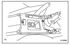
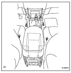
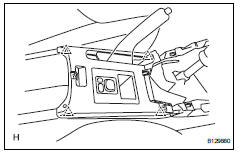
- Remove rear console box sub-assembly
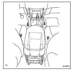
- Remove the console box carpet.
- Remove the 2 bolts and 2 screws.
- Disconnect the connector and remove the rear console box.
- Remove lower instrument panel finish panel
- Remove the 2 screws.
- Using a screwdriver detach the 8 claws and remove the lower instrument panel finish panel.
Hint:
Tape the screwdriver tip before use.
- Remove no. 2 Instrument panel under cover sub-assembly
- Detach the 2 claws and remove the instrument panel under cover.
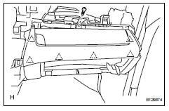
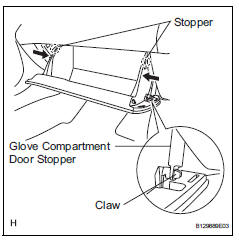
- Remove glove compartment door assembly
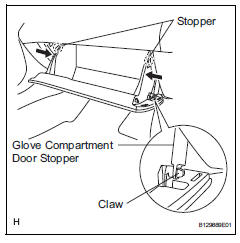
- Open the glove compartment door.
- Detach the claw from the glove compartment door stopper.
- While pushing in the sides of the glove compartment door as indicated by the arrows in the illustration, open the door to release it from the 2 stoppers.
- Open the door until it is horizontal.
- Pull the glove compartment door toward the rear of the vehicle to detach the 2 hinges and remove the glove compartment door.
- Remove no. 1 Switch hole base
- Using a screwdriver, detach the 4 clips.
- Disconnect the connectors and remove the switch hole base.
- Remove instrument panel safety pad cover
- Using a screwdriver, detach the 4 claws and remove the instrument panel safety pad cover.
Hint:
Tape the screwdriver tip before use.
- Remove instrument panel box
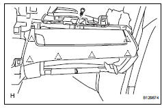
- Remove the screw.
- Using a screwdriver, detach the 6 clips and remove the instrument panel box.
Hint:
Tape the screwdriver tip before use.
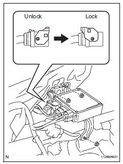
- Remove power steering ecu assembly
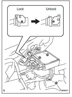
- Disconnect the connectors.
- Remove the 3 nuts and ecu.
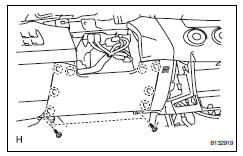
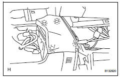
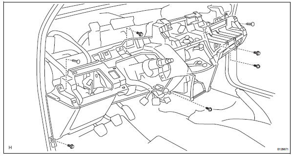
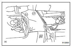
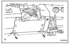
- Remove lower instrument panel
- Remove the 2 bolts, 3 screws and 2 clips.
- Disconnect the connectors and clamps and remove the lower instrument panel.
Disassembly
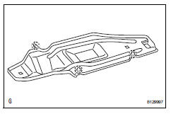
- Remove glove compartment door stopper sub-assembly
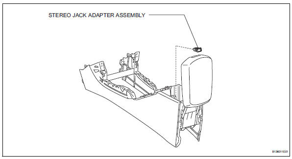
- Remove stereo jack adapter assembly
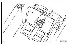
- Detach the 2 claws and remove the stereo jack adapter.
Reassembly
- Install stereo jack adapter assembly
- Attach the 2 claws to install the stereo jack adapter.
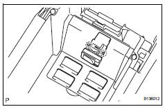
- Install glove compartment door stopper sub-assembly
Installation
- Install lower instrument panel
- Connect the connectors and clamps and install the lower instrument panel.
- Install the 2 bolts, 3 screws and 2 clips.

- Install power steering ecu assembly
- Install the ecu with the 3 nuts.
- Connect the connectors.
- Install instrument panel box
- Attach the 6 clips to install the instrument panel box.
- Install the screw.
- Install instrument panel safety pad cover
- Attach the 4 claws to install the instrument panel safety pad cover.
- Install no. 1 Switch hole base
- Connect the connectors.
- Attach the 4 clips to install the switch hole base.
- Install glove compartment door assembly
- Attach the 2 hinges to install the door.
- Attach the claw to the glove compartment door stopper.
- While pushing in the sides of the glove compartment door as indicated by the arrows in the illustration, close the door to engage it to the 2 stoppers.
- Install no. 2 Instrument panel under cover sub-assembly
- Attach the 2 claws to install the instrument panel under cover.
- Install lower instrument panel finish panel
- Attach the 8 claws to install the lower instrument panel finish panel.
- Install the 2 screws.
- Install rear console box sub-assembly
- Connect the connector.
- Install the rear console box with the 2 bolts and 2 screws.
- Install the console box carpet.
- Install no. 1 Instrument panel bracket cover inner lh
- Attach the 2 claws to install the instrument panel bracket cover.
- Install no. 1 Instrument panel bracket cover inner rh
- Attach the 2 claws to install the instrument panel bracket cover.
- Install console rear end panel
- Attach the 6 claws to install the console rear end panel.
- Install console rear end panel (rse type)
- Attach the 2 clips and 4 claws to install the console rear end panel.
- Install upper rear console panel subassembly
- Connect the connector.
- Attach the 4 clips to install the upper rear console panel.
- Install console cup holder box
- Attach the 2 clips to install the cup holder box.
- Install the 2 screws.
- Install switch base
- Connect the connectors.
- Attach the 2 clips and 2 claws to install the switch base.
- Install upper console panel sub-assembly
- Connect the connector.
- Attach the 2 clips and 4 claws to install the upper console panel.
- Install the shift lever knob.
- Install no. 2 Console upper panel garnish
- Attach the 4 clips to install the upper panel garnish.
- Install no. 1 Console upper panel garnish
- Attach the 4 clips to install the upper panel garnish.
- Install heater control sub-assembly (for automatic air conditioning system) (see page ac- 241)
- Install heater control sub-assembly (for manual air conditioning system) (see page ac-244)
- Install windshield wiper switch assembly
- Install headlight dimmer switch assembly
- Install spiral cable sub-assembly (see page rs-347)
- Install steering column cover (see page sr- 20)
- Install steering wheel assembly (see page sr-21)
- Install steering pad assembly (see page rs- 336)
- Install instrument panel sub-assembly
- Install the instrument panel (see page ip-9).
- Connect cable to negative battery terminal
- Check srs warning light
- Check the srs warning light (see page rs-37).
 Installation
Install upper instrument panel
Attach the 6 clips and 5 claws to install the
instrument panel.
Connect the connectors and clamps.
Install the 2 bolts and 2 screws.
Connect the ...
 Suspension
...
Other materials:
Diagnosis system
Description
Key reminder warning system data can be read
through the data link connector 3 (dlc3) of the
vehicle. When the system seems to be
malfunctioning, use the intelligent tester (with can
vim) to check for malfunctions and perform repairs.
Check dlc3
The vehi ...
High mounted stop light assembly
Components
Removal
Disconnect cable from negative battery
terminal
Caution:
Wait at least 90 seconds after disconnecting the
cable from the negative (-) battery terminal to
prevent airbag and seat belt pretensioner activation.
Remove back door center garnish (see page
ed-59)
...
Rear no. 2 Suspension arm
Components
Removal
Hint:
Use the same procedures for the rh side and lh side.
The procedures listed below are for the lh side.
Remove rear wheel
Disconnect no. 2 Parking brake cable
assembly (see page pb-8)
Disconnect skid control sensor wire (for
2wd) (see page bc-198)
D ...
