Toyota RAV4 (XA40) 2013-2018 Service Manual: Installation
Toyota RAV4 (XA40) 2013-2018 Service Manual / Instrument panel / Upper instrument panel / Installation
- Install upper instrument panel
- Attach the 6 clips and 5 claws to install the instrument panel.
- Connect the connectors and clamps.
- Install the 2 bolts and 2 screws.
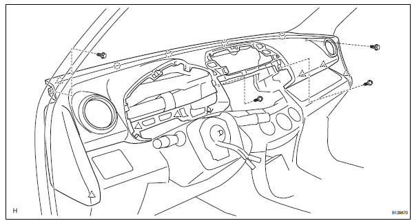
- Connect the passenger airbag connector.
- Install the 2 bolts to the passenger airbag.
Torque: 20 n*m (204 kgf*cm, 15 ft.*Lbf)
- Install front pillar garnish lh (see page ir- 57)
- Install front pillar garnish rh (see page ir- 58)
- Install glove compartment door assembly (see page ip-25)
- Install instrument panel register assembly center
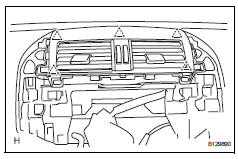
- Attach the 5 clips to install the instrument panel register.
- Install radio receiver
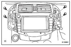
- Connect the connectors.
- Attach the 4 clips to install the radio receiver.
- Install the 4 bolts.
- Install no. 1 Instrument cluster finish panel center
- Connect the connector.
- Attach the 3 clips and 3 claws to install the cluster finish panel.
- Install no. 2 Instrument cluster finish panel center
- Connect the connector.
- Attach the 3 clips and 3 claws to install the cluster finish panel.
- Install combination meter assembly
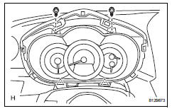
- Connect the connector.
- Attach the 2 clips to install the combination meter.
- Install the 2 screws.
- Install instrument cluster finish panel sub-assembly
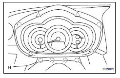
- Attach the 4 clips and 6 claws to install the instrument cluster finish panel.
- Connect cable to negative battery terminal
- Check srs warning light
- Check the srs warning light (see page rs-37).
 Reassembly
Install cooler (solar sensor) thermistor
(for automatic air conditioning system)
Install automatic light control sensor
(for automatic light control system)
Install front passenger airbag a ...
 Lower instrument panel
Precaution
Precaution for vehicle with srs airbag and
seat belt pretensioner
Some operations in this section may affect the srs
airbags and seat belt pretensioner. Prior to
performing ...
Other materials:
Voice command system
The voice command system enables the hands-free system to
be operated using voice commands.
Using the voice command system
Press the talk switch.
To cancel the voice command system,
press and hold the talk switch.
After a beep sounds, say the desired command.
On the list screen, ...
Problem symptoms table
Hint:
Use the table below to help determine the cause of the
problem symptom. The potential causes of the symptoms
are listed in order of probability in the "suspected area"
column of the table. Check each symptom by checking the
suspected areas in the order they are listed. Re ...
Components
...
© 2011-2026 Copyright www.trav4.net
