Toyota RAV4 (XA40) 2013-2018 Service Manual: Rear speed sensor (for 4wd)
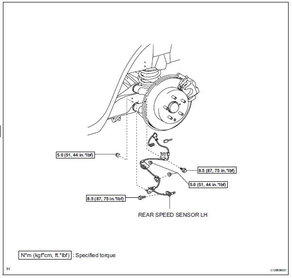
Components
Removal
Hint:
- Use the same procedures for the lh side and rh side.
- The procedures listed below are for the lh side.
- Disconnect cable from negative battery terminal
Caution:
Wait at least 90 seconds after disconnecting the cable from the negative (-) battery terminal to prevent airbag and seat belt pretensioner activation.
- Remove rear wheel
- Remove deck trim side panel assembly lh
- Remove the deck trim side panel lh (see page ir- 26).
Hint:
Refer to the procedures from the removal of the rear door scuff plate lh up until the removal of the deck trim side panel assembly lh.
- Remove rear speed sensor lh
- Disconnect the speed sensor connector.
- Disconnect the grommet of the speed sensor wire from the hole of the wheel house.
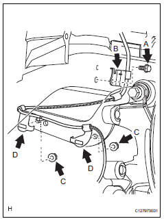
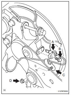
- Remove the bolt (labeled a) and sensor clamp (labeled b) from the side member.
- Remove the 2 nuts (labeled c) and sensor clamps (labeled d) from the upper arm.
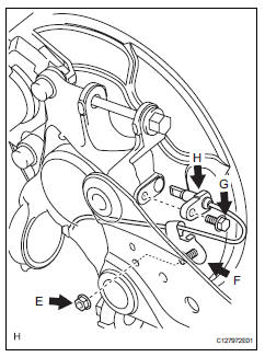
- Remove the nut (labeled e) and sensor clamp (labeled f) from the trailing arm.
- Remove the bolt (labeled g) and sensor body (labeled h) from the carrier.
Notice:
Keep the sensor tip and sensor installation hole free from foreign matter.
Inspection
- Inspect rear speed sensor
- Check the speed sensor. If any of the following occurs, replace the speed sensor with a new one.
- The surface of the speed sensor is cracked, dented, or chipped off.
- The connector or wire harness is scratched, cracked, or damaged.
- The speed sensor has been dropped.
Installation
Hint:
- Use the same procedures for the lh side and rh side.
- The procedures listed below are for the lh side.
- Install rear speed sensor lh
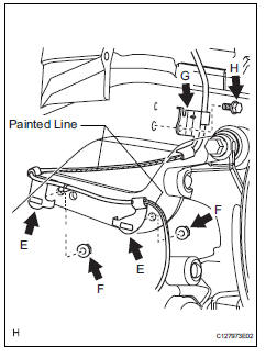
Notice:
To prevent interference with other parts, do not twist the sensor wire's painted line areas when installing it.
- Install the sensor (labeled a) with the bolt (labeled b).
Torque: 8.5 N*m (87 kgf*cm, 75 in.*Lbf)
Notice:
- Keep the sensor tip and sensor installation hole free from foreign matter.
- To prevent interference with the bearing rotor, do not rotate the sensor body when inserting the sensor body or after inserting the sensor body.
- Install the sensor clamp (labeled c) with the nut (labeled d).
Torque: 5.0 N*m (51 kgf*cm, 44 in.*Lbf)
- Install the sensor clamps (labeled e) with the 2 nuts (labeled f).
Torque: 5.0 N*m (51 kgf*cm, 44 in.*Lbf)
Notice:
Do not twist the sensor wire when installing the clamps.
- Install the sensor clamp (labeled g) with the bolt (labeled h).
Torque: 8.5 N*m (87 kgf*cm, 75 in.*Lbf)
Notice:
Do not twist the sensor wire when installing the clamp.
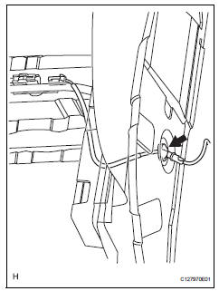
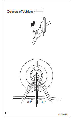
- Insert the connector and grommet to the inside of the vehicle through the passage hole in the wheel house.
Notice:
Make sure the grommet's band clamp remains on the outside of the vehicle.
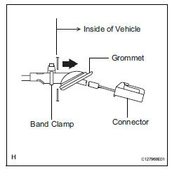
- Hold the grommet and pull it from the inside of the vehicle to the outside of the vehicle. Then fix it in place so that it is not tilted.
Notice:
- When pulling out the grommet, do not grip the sensor wire.
- Fix the grommet in place within the range shown in the illustration.
- Connect the speed sensor connector.
- Install deck trim side panel assembly lh
- Install the deck trim side panel lh (see page ir-49).
Hint:
Refer to the procedures from the installation of the deck trim side panel lh up until the installation of the rear door scuff plate lh.
- Install rear wheel
Torque: 103 n*m (1,050 kgf*cm, 76 ft.*Lbf)
- Connect cable to negative battery terminal
- Check speed sensor signal
- Check the speed sensor signal (see page bc-28).
 Skid control sensor (for 2wd)
Components
Removal
Hint:
Use the same procedures for the lh side and rh side.
The procedures listed below are for the lh side.
Disconnect cable from negative battery
terminal
Ca ...
 Yaw rate and deceleration sensor
Components
Removal
Disconnect cable from negative battery
terminal
Caution:
Wait at least 90 seconds after disconnecting the
cable from the negative (-) battery terminal to
prevent ai ...
Other materials:
Tc and cg terminal circuit
Description
Dtc output mode is set by connecting terminals tc and cg of the dlc3.
The dtcs are displayed by blinking the srs warning light.
Hint:
Make sure that dtc b1281 has not been output. If dtc b1281 has been
output, refer to the multiplex
communication system.
When each warning ...
Operating an ipod
Connecting an ipod enables you to enjoy music from the vehicle
speakers.
Connecting an ipod
Open the cover and connect
an ipod using an ipod cable.
Turn on the power of the ipod if
it is not turned on.
Press the ÔÇťmediaÔÇŁ button repeatedly until ÔÇťipodÔÇŁ is displayed.
...
Data list / active test
Read data list
Hint:
Using the intelligent tester's data list allows switch,
sensor, actuator, and other item values to be read
without removing any parts. Reading the data list
early in troubleshooting is one way to save time.
Notice:
In the table below, the values listed under "no ...
