Toyota RAV4 (XA50) 2019-2026 Owners Manual: Luggage compartment features
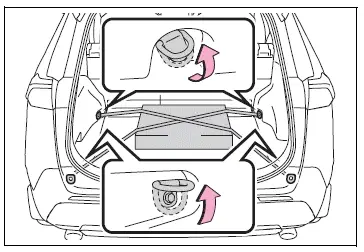
Cargo hooks
Raise the hook to use.
The cargo hooks are provided for securing loose items.
WARNING
â– When cargo hooks are not in use
To avoid injury, always return the hooks to their stowed positions when not in use.
Deck board
â– Flipping the deck board upside down
The deck board can be flipped upside down (resin side up) depending on the situation.
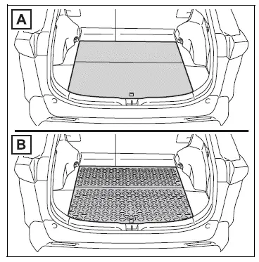
- Original position
- Underside (resin side)
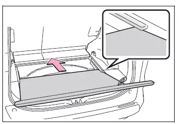
â– Changing the deck board positions
Height of the deck board can be changed by setting the deck board under the floor.
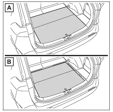
- Upper
- Lower
1. Pull up the tab to raise the deck board and move it toward you to remove.
2. Place the deck board through the groove and move forward.
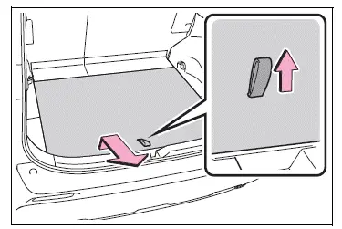
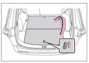
â– Setting the deck board upright
When taking out the tools, the deck board can be set upright.
When the back surface (resin surface) of the deck board is facing up, flip it back to the original position.
1. Pull up the tab to raise the deck board and fold it forward.
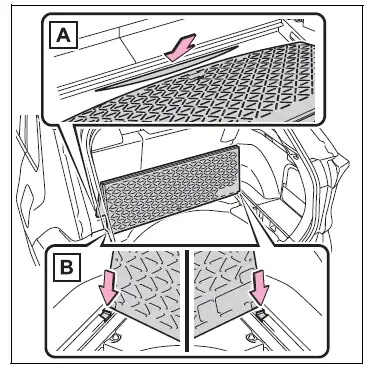
2. Place the edge into the groove (A), and with the deck board in a standing state, put the edge into the holes (B).
WARNING
â– When operating the deck board
Do not place anything on the deck board when operating the board.
Otherwise, your fingers may be caught or an accident may result causing injuries.
â– Caution while driving
Keep the deck board closed.
In the event of sudden braking, an accident may occur due to an occupant being struck by the deck board or the items stored under the deck board.
Side auxiliary box
Type A
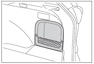
Type B
â– Removing the partition plate
Disengage the claws
 List of storage features
Location of the storage features
Open tray
Auxiliary boxes
Bottle holders
Console box
Cup holders
Glove box
WARNING
â– Items that should not be left
in the vehicle
Do not leave glasses, light ...
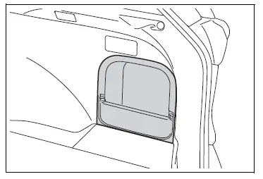
 Luggage cover (if
equipped)
Luggage cover (if
equipped)
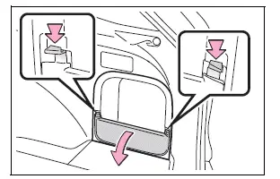
â– Installing the luggage cover
1. Compress the both ends of
the luggage cover and insert
into the recess to install.
2. Pull out the luggage cover
and hook it onto the anchors.
â– Removing the lu ...
Other materials:
Driver side - side airbag sensor assembly initialization incomplete
Description
The side airbag sensor lh consists of part including the diagnostic circuit
and the lateral deceleration
sensor.
When the center airbag sensor receives signals from the lateral deceleration
sensor, it determines
whether or not the srs should be activated.
Dtc b1623/81, b ...
Dtc check / clear
Check dtc
Dtcs which are stored in the ecm can be displayed
with the intelligent tester.
The intelligent tester can display pending dtcs and
current dtcs. Some dtcs are not stored unless a
malfunction is detected in consecutive driving
cycles. When a malfunction is detected ...
Communication
Description
When a key is inserted into the ignition key cylinder but no communication
occurs between the key and
transponder key ecu, dtc b2796 is output. When a key is inserted into the
ignition key cylinder but a
communication error occurs between the key and transponder key ecu, dtc b ...
