Toyota RAV4 (XA40) 2013-2018 Service Manual: Yaw rate and deceleration sensor
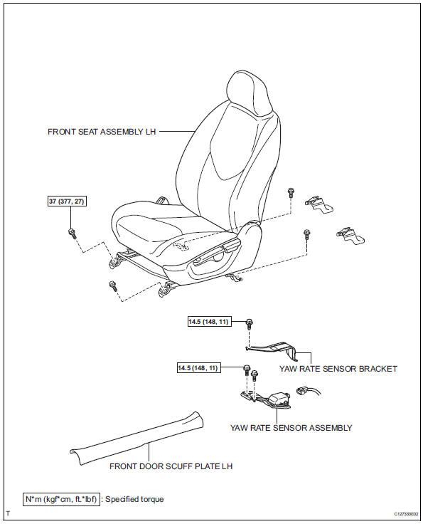
Components
Removal
- Disconnect cable from negative battery terminal
Caution:
Wait at least 90 seconds after disconnecting the cable from the negative (-) battery terminal to prevent airbag and seat belt pretensioner activation.
- Remove front seat assembly lh
- For manual seat: remove the front seat lh (see page se-11).
- For power seat: remove the front seat lh (see page se-27).
- Remove front door scuff plate lh (see page ir-26)
- Remove yaw rate sensor bracket
- Remove the bolt and yaw rate sensor bracket.
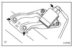
- Remove yaw rate sensor assembly
- Disconnect the yaw rate sensor connector.
- Remove the 2 bolts and yaw rate sensor.
Notice:
Do not remove the sensor from the bracket.
Inspection
- Inspect yaw rate sensor
- Inspect the yaw rate sensor. If any of the following occurs, replace the yaw rate sensor with a new one.
- The surface of the sensor is cracked, dented, or chipped.
- The connector or wire harness is scratched, cracked, or damaged.
- The sensor has been dropped.
Installation
- Install yaw rate sensor assembly
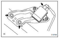
- Install the yaw rate sensor with the 2 bolts.
Torque: 14.5 N*m (148 kgf*cm, 11 ft.*Lbf)
Notice:
- Do not damage the yaw rate sensor.
- Make sure that the yaw rate sensor is installed securely.
- Connect the yaw rate sensor connector.
- Install yaw rate sensor bracket
- Install the bracket with the bolt.
Torque: 14.5 N*m (148 kgf*cm, 11 ft.*Lbf)
- Install front door scuff plate lh (see page ir-59)
- Install front seat assembly lh
- For manual seat: install the front seat (see page se-22).
- For power seat: install the front seat (see page se-37).
- Connect cable to negative battery terminal
- Perform zero point calibration of yaw rate and deceleration sensor
- Perform the yaw rate and deceleration sensor zero point calibration (see page bc-24).
- Inspect yaw rate sensor signal
- Inspect the yaw rate sensor signal (see page bc- 28).
 Rear speed sensor (for 4wd)
Components
Removal
Hint:
Use the same procedures for the lh side and rh side.
The procedures listed below are for the lh side.
Disconnect cable from negative battery
terminal
Ca ...
 Steering angle sensor
Components
Removal
Precaution
Caution:
Be sure to read the "precaution" thoroughly
before servicing (see page rs-1).
Disconnect cable from negative battery
terminal
Ca ...
Other materials:
Removal
(2005/11-2006/01)
Remove front wheel
Drain automatic transaxle fluid
Drain the automatic transaxle fluid for u140f (see
page ax-147).
Drain the automatic transaxle fluid for u241e (see
page ax-146).
Remove front axle hub nut (see page ah-6)
Disconnect front speed sensor lh (see page
bc-191) ...
Problem symptoms table
Hint:
Use the table below to help determine the cause of the
problem symptom. The potential causes of the symptoms
are listed in order of probability in the "suspected area"
column of the table. Check each symptom by checking the
suspected areas in the order they are listed. Re ...
Transmission wire
Components
Removal
Disconnect cable from negative battery
terminal
Caution:
Wait at least 90 seconds after disconnecting the
cable from the negative (-) battery terminal to
prevent airbag and seat belt pretensioner activation.
Remove no. 1 Engine under cover
Drain automati ...
