Toyota RAV4 (XA40) 2013-2018 Service Manual: Only passenger door lock / unlock functions do not operate
Description
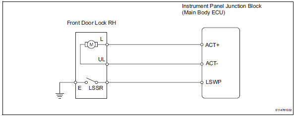
The main body ecu receives lock / unlock switch signals and activates the door lock motor accordingly.
Wiring diagram
Inspection procedure
- Read value of intelligent tester (lock position switch)
- Use the data list to check if the door lock is functioning properly.
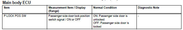
Ok: when the door lock is operating, the intelligent tester should display as shown in the table.

- Inspect front door with motor lock assembly rh
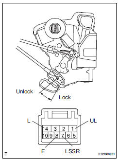
- Apply the battery voltage to the door lock motor and check the operation of the door lock motor.
Ok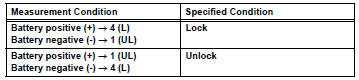
- Measure the resistance of the door lock position switch.
Standard resistance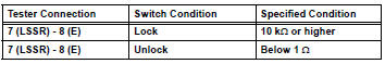

- Check wire harness (door lock - ecu)
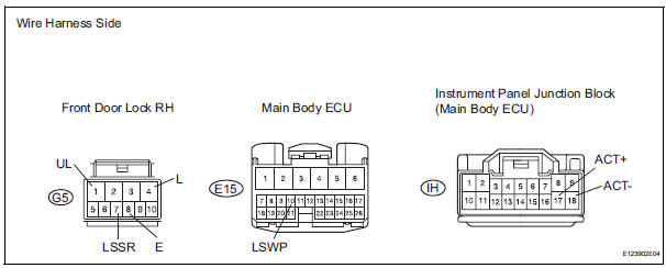
- Disconnect the g5 door lock connector.
- Disconnect the e15 ecu connector.
- Disconnect the ih junction block connector.
- Measure the resistance of the wire harness side connectors.
Standard resistance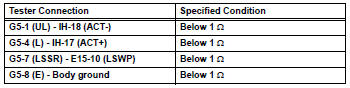

Replace instrument panel junction block (main body ecu)
 Only driver door lock / unlock functions do not operate
Description
The main body ecu receives lock / unlock switch signals and activates the
door lock motor accordingly.
Wiring diagram
Inspection procedure
Perform active test by intelligent t ...
 Only rear door lh lock / unlock functions do not operate
Description
The main body ecu receives lock / unlock switch signals and activates the
door lock motor accordingly.
Wiring diagram
Inspection procedure
Inspect rear door with motor lock as ...
Other materials:
Outer rear view mirror
Components
Removal
Hint:
Use the same procedures for the lh side and rh side.
The procedures listed below are for the lh side.
Remove front door lower frame bracket
garnish lh (see page ed-19)
Remove front armrest upper base panel
lh (see page ed-19)
Remove front door t ...
Headlight relay circuit
Description
When the light control switch, located on the headlight dimmer switch, is
turned to the head position, the
head relay illuminates the headlights.
Wiring diagram
Inspection procedure
Perform active test by intelligent tester (headlight)
Connect the intelligent tester ( ...
Front power seat lumbar switch
Inspection
Inspect front power seat lumbar switch lh
Measure the resistance between the terminals when
the switch is operated.
Standard resistance
If the result is not as specified, replace the switch. ...
