Toyota RAV4 (XA40) 2013-2018 Service Manual: Only driver door lock / unlock functions do not operate
Description
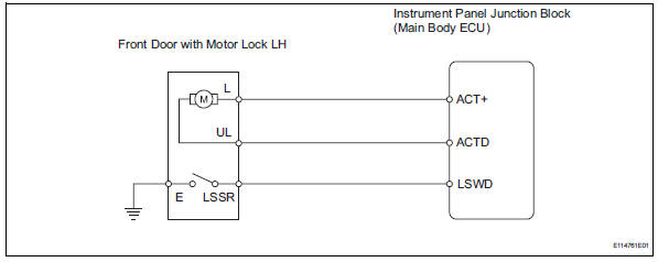
The main body ecu receives lock / unlock switch signals and activates the door lock motor accordingly.
Wiring diagram
Inspection procedure
- Perform active test by intelligent tester (door lock)
- Select the active test, use the intelligent tester to generate a control command, and then check that the doors lock / unlock.
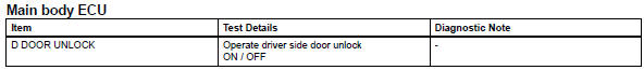
Ok: doors can lock / unlock

- Read value of intelligent tester (lock position switch)
- Use the data list to check if the door lock is functioning properly.
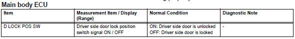
Ok: when the door lock is operating, the intelligent tester should display as shown in the table.

- Inspect front door with motor lock assembly lh
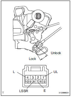
- Apply the battery voltage to the motor terminals and check the operation of the door lock motor.
Ok 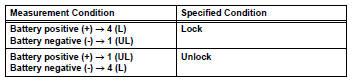
- Measure the resistance of the door lock position switch.
Standard resistance 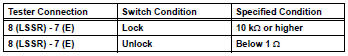

- Check wire harness (door lock - ecu)
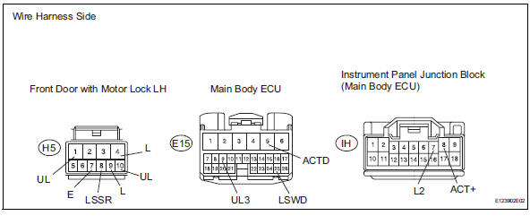
- Disconnect the h5 door lock connector.
- Disconnect the e15 ecu connector.
- Disconnect the ih junction block connector.
- Measure the resistance of the wire harness side connectors.
Standard resistance 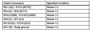

Replace instrument panel junction block (main body ecu)
 All doors cannot be locked / unlocked simultaneously
Description
The main body ecu receives switch signals from the door control switch on the
power window regulator
master switch, door control switch and driver side door key cylinder, and
activat ...
 Only passenger door lock / unlock functions do not operate
Description
The main body ecu receives lock / unlock switch signals and activates the
door lock motor accordingly.
Wiring diagram
Inspection procedure
Read value of intelligent tester (lo ...
Other materials:
Theft deterrent system
Engine immobilizer system
The vehicle’s keys have built-in transponder chips that prevent
the engine from starting if a key has not been previously registered
in the vehicle’s on-board computer.
Never leave the keys inside the vehicle when you leave the vehicle.
This system is designed to ...
Disassembly
Remove radiator grille sub-assembly
Remove the 4 bolts and 4 nuts.
Detach the 6 claws and remove the radiator grille.
Remove no. 1 Radiator grille lower
Detach the 18 claws and remove the radiator grille.
Remove no. 2 Radiator grille lower
Detac ...
Short in front passenger side squib 2nd step circuit
Description
The front passenger side squib 2nd step circuit consists of the center airbag
sensor and the front
passenger airbag.
The circuit instructs the srs to deploy when the deployment conditions are met.
These dtcs are recorded when a malfunction is detected in the front passenger ...
