Toyota RAV4 (XA40) 2013-2018 Service Manual: All doors cannot be locked / unlocked simultaneously
Description
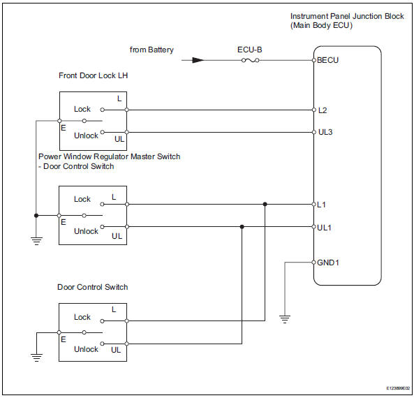
The main body ecu receives switch signals from the door control switch on the power window regulator master switch, door control switch and driver side door key cylinder, and activates the door lock motor on each door accordingly.
Wiring diagram
Inspection procedure
- Perform active test by intelligent tester (door lock)
- Select the active test, use the intelligent tester to generate a control command, and then check that the doors lock / unlock.
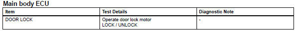
Ok: doors can lock / unlock.

- Inspect fuse (ecu-b)
- Remove the ecu-b fuse from the engine room no. 2 Relay block.
- Measure the resistance.
Standard resistance:
below 1


- Check wire harness (ecu - battery and body ground)
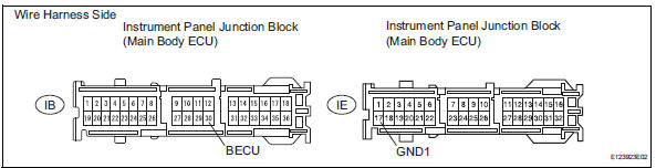
- Disconnect the ih and ie junction block connectors.
- Measure the voltage of the wire harness side connector.
Standard voltage 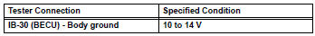
- Measure the resistance of the wire harness side connector.
Standard resistance 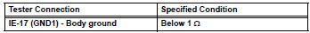

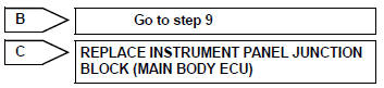
Replace instrument panel junction block (main body ecu)
- Inspect all doors lock / unlock operation
- All doors can be locked/unlocked at once using the following:
- Door control switch on the master switch (switch operation)
- Door control switch on the front passenger side (switch operation).
- Door key cylinder linked with door lock on the driver side (key operation)
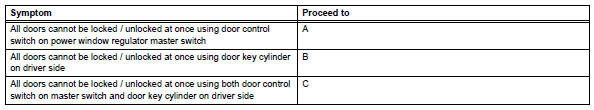
- Proceed to the next step according to the symptom if all the doors cannot be locked / unlocked at once.
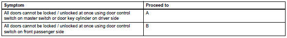

- Inspect driver side door lock / unlock operation
- Proceed to the next step according to the symptom listed in the table below.

- Read value of intelligent tester (door control switch on master switch)
- Use the data list to check if the door control switch is functioning properly.
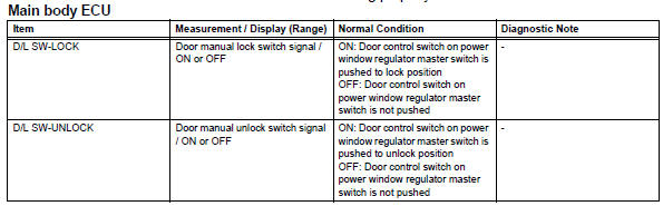
Ok: when the switch is operating, the intelligent tester should display as shown in the table.

- Inspect power window regulator master switch assembly (door control switch)
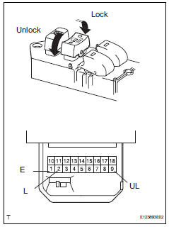
- Remove the master switch.
- Measure the resistance of the door control switch.
Standard resistance 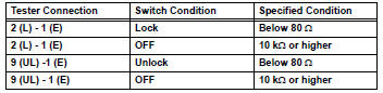

- Check wire harness (master switch - ecu and body ground)
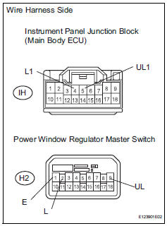
- Disconnect the h2 master switch connector.
- Disconnect the ih junction block connector.
- Measure the resistance of the wire harness side connectors.
Standard resistance 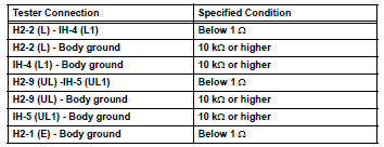

Replace instrument panel junction block (main body ecu)
- Read value of intelligent tester (door key switch)
- Use the data list to check if the door key is functioning properly.
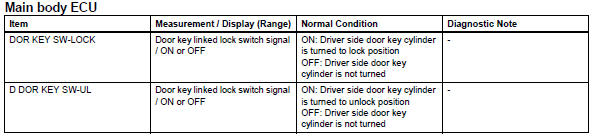
Ok: when the door key is operating, the intelligent tester should display as shown in the table.

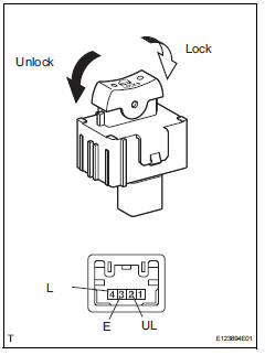
- Inspect front door with motor lock assembly lh
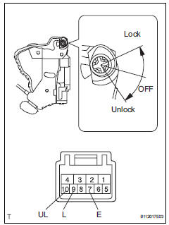
- Remove the front door lock.
- Measure the resistance of the door lock and unlock switch.
Standard resistance 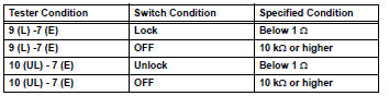

- Check wire harness (motor - ecu and body ground)
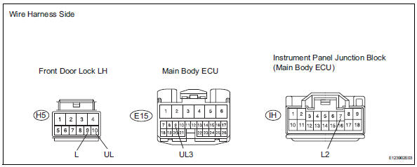
- disconnect the h5 door lock motor connector.
- Disconnect the e15 ecu connector.
- Disconnect the ih junction block connector.
- Measure the resistance of the wire harness side connectors.
Standard resistance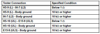

Replace instrument panel junction block (main body ecu)
- Inspect door control switch assembly
- Remove the control switch.
- Measure the resistance of the door control switch.
Standard resistance 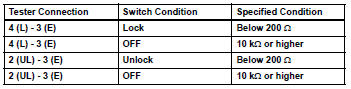

- Check wire harness (switch - ecu and body ground)
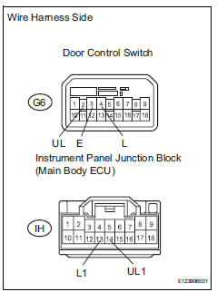
- Disconnect the g6 switch connector.
- Disconnect the ih junction block connector.
- Measure the resistance of the wire harness side connectors.
Standard resistance 

Replace instrument panel junction block (main body ecu)
 Data list / active test
Read data list
Hint:
Using the intelligent tester's data list allows switch,
sensor, actuator and other item values to be read without
removing any parts. Reading the data list early in
trou ...
 Only driver door lock / unlock functions do not operate
Description
The main body ecu receives lock / unlock switch signals and activates the
door lock motor accordingly.
Wiring diagram
Inspection procedure
Perform active test by intelligent t ...
Other materials:
Room light assembly
Components
Removal
Disconnect cable from negative battery
terminal
Caution:
Wait at least 90 seconds after disconnecting the
cable from the negative (-) battery terminal to
prevent airbag and seat belt pretensioner activation.
Remove room light lens
Using a screwdriver ...
Before driving
Floor mat
Use only floor mats designed specifically for vehicles of the same
model and model year as your vehicle. Fix them securely in place
onto the carpet.
Insert the retaining hooks (clips)
into the floor mat eyelets.
Turn the upper knob of each
retaining hook (clip) to secure
t ...
Cargo and luggage
Take notice of the following
information about storage
precautions, cargo capacity
and load.
WARNING
â– Things that must not be carried
in the luggage compartment
The following things may cause a
fire if loaded in the luggage compartment:
Receptacles containing gasoline
Aerosol cans
â– Storage p ...
