Toyota RAV4 (XA40) 2013-2018 Service Manual: Removal
- Remove package tray trim pocket subassembly (w/o rear no. 2 Seat)
- Remove tonneau cover assembly (w/o rear no. 2 Seat)
- Remove rear floor no. 1 Board (w/o rear no.
2 Seat)
- Remove deck board assembly (w/o rear no. 2 Seat)
- Remove rear floor no. 3 Board (w/o rear no.
2 Seat)
- Remove rear floor no. 2 Board (w/o rear no.
2 Seat)
- Remove rear floor no. 1 Mat support side plate (w/o rear no. 2 Seat) (see page ir-31)
- Remove back door weatherstrip (w/o rear no. 2 Seat)
- Remove rear floor finish plate (w/o rear no.
2 Seat) (see page ir-31)
- Remove reclining remote control lever bezel lh (w/o rear no. 2 Seat)
- Using a screwdriver, detach the 6 claws and remove the bezel.
Hint:
Tape the screwdriver tip before use.
- Remove tether anchor bracket subassembly (w/o rear no. 2 Seat) (see page ir-32)
- Remove deck trim side panel assembly lh (w/o rear no. 2 Seat) (see page ir-32)
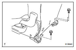
- Remove reclining remote control lever sub-assembly lh (w/o rear no. 2 Seat)

- Remove the 2 bolts and lever.
- Disconnect the rear no. 1 Seat lock cable from the lever.
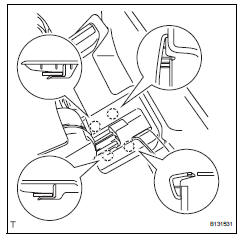
- Remove rear no. 5 Seat leg side cover
- Using a screwdriver, detach the 3 claws and clip, and remove the side cover.
Hint:
Tape the screwdriver tip before use.
- Remove rear no. 4 Seat leg side cover (w/ rear no. 2 Seat)
- Using a screwdriver, detach the 4 claws and remove the side cover.
Hint:
Tape the screwdriver tip before use.
- Remove rear no. 4 Seat leg side cover (w/o rear no. 2 Seat)
- Using a screwdriver, detach the 4 claws and remove the side cover.
Hint:
Tape the screwdriver tip before use.
- Remove rear no. 3 Seat leg side cover (w/ rear no. 2 Seat)
- Using a screwdriver, detach the 4 claws and remove the side cover.
Hint:
Tape the screwdriver tip before use.
- Remove rear no. 3 Seat leg side cover (w/o rear no. 2 Seat)
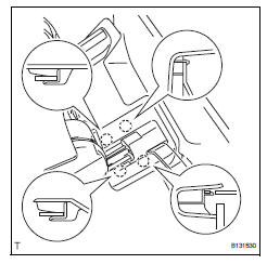
- Using a screwdriver, detach the 4 claws and remove the side cover.
Hint:
Tape the screwdriver tip before use.
- Remove rear seat leg cover
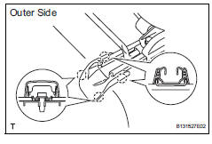
- Using a screwdriver, detach the 8 claws and remove the 2 leg covers.
Hint:
Tape the screwdriver tip before use.
- Remove rear seat lap type belt assembly center rh (w/ rear no. 2 Seat) (see page sb-39)
- Remove rear seat lap type belt assembly center rh (w/o rear no. 2 Seat) (see page sb-39)
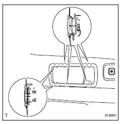
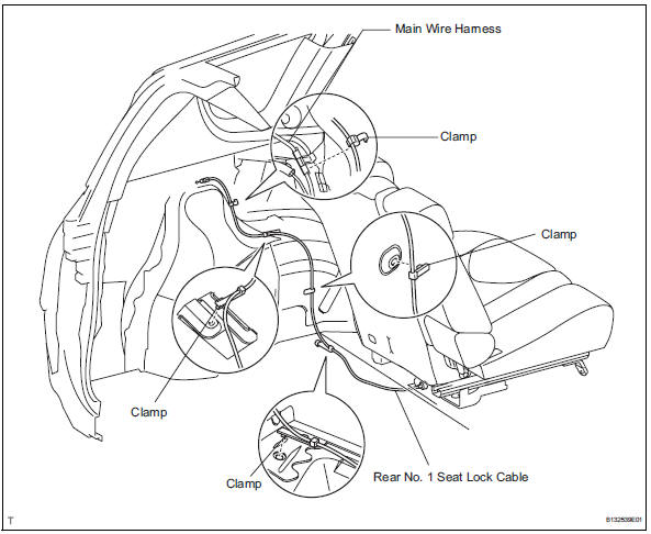
- Remove rear no. 1 Seat lock cable assembly (w/o rear no. 2 Seat)
- Disconnect the lock cable from the seat.
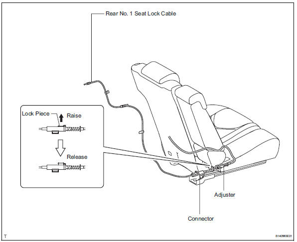
- Raise the adjuster's lock piece to release the lock.
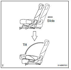
- Slide the seat forward and tilt the seatback forward.
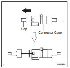
- Remove the seat's cap from the connector case.
- Pull the seat's cap toward the outside of the vehicle. Then remove the cable from the connector case's slit.

- Remove the body's cap from the connector case.
- Detach the clamps and remove the lock cable.
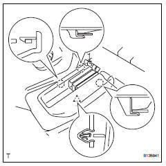
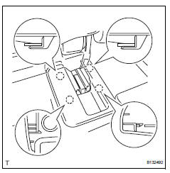
- Remove rear no. 1 Seat assembly lh
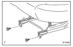
- Lift up the seat track adjusting handle and move the seat to the rearmost position.
- Remove the 2 bolts on the front side of the seat.
- Lift up the seat track adjusting handle and move the seat to the foremost position.
- Remove the 3 bolts on the rear side of the seat.
- Fully tilt the seatback forward. Then remove the seat.
Notice:
Be careful not to damage the vehicle body,
 Rear no. 1 Seat assembly (for lh side)
Components
...
 Disassembly
Caution:
Wear protective gloves. Sharp areas on the seatback
frame, seat cushion frame and reclining adjuster may
injure your hands.
Remove rear seat headrest assembly
Remove rear seat center ...
Other materials:
Rear coil spring
Components
Removal
Hint:
Use the same procedures for the rh side and lh side.
The procedures listed below are for the lh side.
Remove rear wheel
Remove skid control sensor wire (for 2wd)
(see page bc-198)
Remove rear speed sensor lh (for 4wd) (see
page bc-205)
Disconnect ...
Catalyst monitor (active air-fuel ratio control type)
Preconditions
The monitor will not run unless:
The mil is off.
Drive pattern
Connect the intelligent tester to the dlc3.
Turn the ignition switch on.
Turn the tester on.
Clear dtcs (if set) (see page es-35).
Start the engine and warm it up.
Drive the vehicle at be ...
Reassembly (2006/01- )
Install front drive shaft bearing (for rh)
Install the bearing bracket snap ring to the inboard
shaft.
Using sst and a press, press in the drive shaft
bearing to the inboard joint rh.
Sst 09527-10011, 09710-04081
Notice:
The bearing should be installed completely.
Usi ...
