Toyota RAV4 (XA40) 2013-2018 Service Manual: Parts location
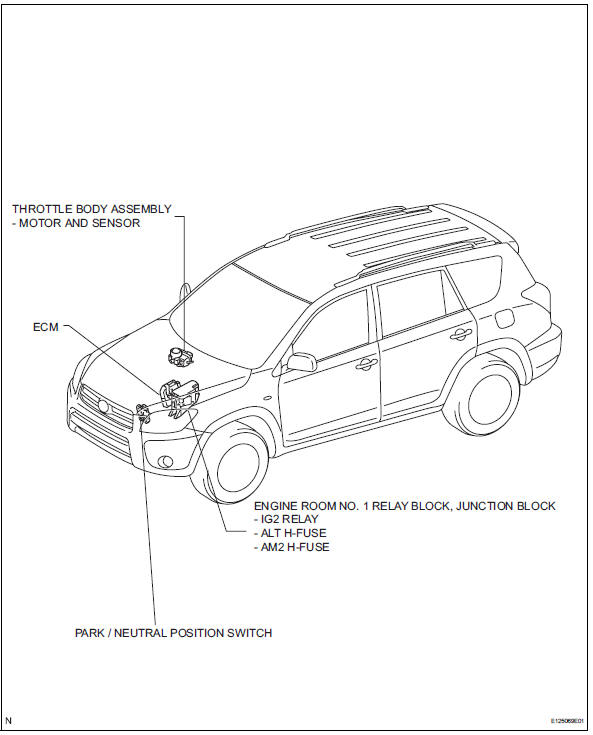
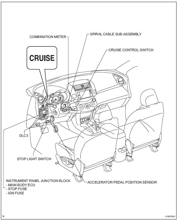
System diagram
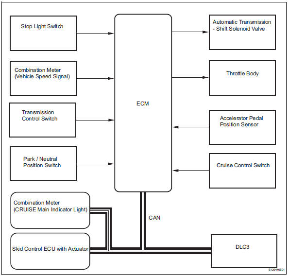
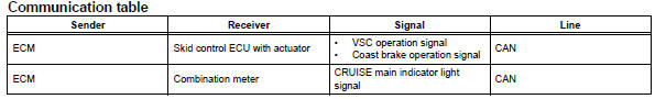
System description
- Cruise control system
This system is controlled by the ecm, and is activated by the throttle position sensor and motor. The ecm controls the following functions: on-off, set / coast, resume / accel, cancel, vehicle speed operation, motor output control, and overdrive control.
- The ecm compares the driving vehicle speed from the combination meter with the stored vehicle speed set through the cruise control switch. The ecm controls the throttle valve motor of the throttle body to open the valve when the driving speed is less than the stored speed.
- The ecm receives signals such as on-off, set / coast, resume / accel, and cancel from the cruise control switch.
- The ecm illuminates the combination meter cruise main indicator light when it receives the cruise control switch on signal.
- The ecm cancels the cruise control system when the brake pedal is depressed and the ecm receives the stop light switch signal.
- The ecm cancels the cruise control system when the shift lever is moved from d or 3 to a position other than d or 3, and the ecm receives the pnp switch signal.
- Limit control
- Low speed limit
the lowest possible limit of the speed setting range
is set at approximately 40 km/h (25 mph). The
cruise control system cannot be set when the
driving vehicle speed is below the low speed limit.
Cruise control operation will be automatically canceled when the vehicle speed decreases below the low speed limit 40 km/h (25 mph) while the cruise control is in operation.
- High speed limit
the highest possible limit of the speed setting range
is set at approximately 200 km/h (125 mph). The
cruise control system cannot be set when the
driving vehicle speed is over the high speed limit.
Also, +/res cannot be used to increase speed beyond the high speed limit.
- Operation of cruise control
The cruise control switch operates 7 functions: set, coast, tap-down, resume, acceleration (accel), tap-up, and cancel. The set, tap-down and coast functions, and the resume, tap-up and accel functions are operated with the same switch.
The cruise control switch is an automatic return type switch which turns on only when pressed in each arrow direction and turns off when released.
- Set control.
vehicle speed is stored and constant speed control is maintained when pushing the switch to -/set while driving with the cruise control switch on (the cruise main indicator light is illuminated), and the vehicle speed is within the set speed range (between the low and high speed limits).
- Coast control
The ecm changes the cruise control demanding throttle opening angle to 0Đ and decelerates the vehicle when -/set on the cruise control switch is pressed and held while the cruise control system is operating. When the cruise control switch is released from -/set, the vehicle speed is stored and constant speed control is maintained.
Hint:
- The throttle valve is not fully closed due to idle speed control, etc.
- W/ vsc: the brake is also used to decelerate the vehicle.
- Tap-down control
When tapping down the cruise control switch to -/ set (for approximately 0.5 Seconds) while the cruise control system is in operation, the stored vehicle speed decreases each time by approximately 1.6 Km/h (1.0 Mph). When the cruise control switch is released from -/set and the difference between the driving and stored vehicle speed is less than 5 km/h (3 mph), the vehicle speed is stored and constant speed control is maintained.
- Accel control
The throttle valve motor of the throttle position sensor and motor is instructed by the ecm to open the throttle valve when +/res on the cruise control switch is pressed and held while the cruise control system is operating. When the cruise control switch is released from +/res, the vehicle speed is stored and constant speed is maintained.
- Tap-up control
When tapping up the cruise control switch to +/res (for approximately 0.5 Seconds) while the cruise control system is in operation, the stored vehicle speed increases each time by approximately 1.6 Km/h (1.0 Mph). However, when the difference between the driving and the stored vehicle speed is more than 5 km/h (approximately 3.1 Mph), the stored vehicle speed will not be changed.
- Resume control
If the cruise control operation was canceled with the stop light switch or the cancel switch, and if driving speed is within the set speed range, setting the cruise control switch to +/res restores the vehicle speed memorized at the time of cancellation, and constant speed is maintained.
- Manual cancel control
Performing any of the following cancels the cruise control system (the stored vehicle speed in the ecm is maintained).
- Depressing the brake pedal
- Moving the shift lever to any position except d or 3
- Pulling the cruise control switch to cancel
- Pushing the cruise control switch off (the stored vehicle speed in the ecm is not maintained)
- Auto cancel (fail-safe)
This system has an automatic cancellation function (failsafe) (see page cc-17).
 Precaution
Handling precaution for cruise control system
Turn the cruise control main switch off when not
using the cruise control system.
Be careful as the vehicle speed increases when
driving do ...
 How to proceed with troubleshooting
Hint:
Use these procedures to troubleshoot the cruise control
system.
*: Use the intelligent tester.
Vehicle brought to workshop
Inspect battery voltage
Standard voltage:
11 ...
Other materials:
Intake air temperature circuit malfunction
Description
The intake air temperature (iat) sensor, mounted on the mass air flow (maf)
meter, monitors the iat.
The iat sensor has a built-in thermistor with a resistance that varies according
to the temperature of the
intake air. When the iat is low, the resistance of the thermist ...
Combination meter ecu communication stop mode
Description
Wiring diagram
Inspection procedure
Notice:
Turn the ignition switch off before measuring the resistances of the
main wire and the branch
wire.
After the ignition switch is turned off, check that the key reminder
warning system and light
reminder warning system ...
Torque converter clutch solenoid circuit
Description
The shift solenoid valve dsl is turned on and off by signals from the ecm to
control the hydraulic
pressure acting on the lock-up relay valve, which then controls operation of the
lock-up clutch.
Fail-safe function:
if the ecm detects a malfunction, it turns the shift sol ...
