Toyota RAV4 (XA40) 2013-2018 Service Manual: How to proceed with troubleshooting
Hint:
- Use these procedures to troubleshoot the cruise control system.
- *: Use the intelligent tester.
- Vehicle brought to workshop

- Inspect battery voltage
Standard voltage: 11 to 14 v
If the voltage is below 11 v, recharge or replace the battery before proceeding.

- Check communication function of can communication system*
- Use the intelligent tester (with can vim) to check if the can communication system is functioning normally.
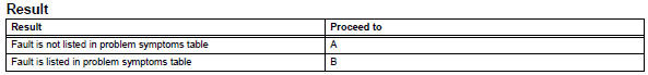
Result: 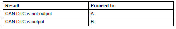

- Check indicator light

- Check dtc*
- Check for a dtc and note any codes that are output.
- Delete the dtc.
- Recheck for dtcs, and try to prompt the dtc by simulating the original activity that the dtc suggests.
Result 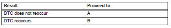


- Overall analysis and troubleshooting*
- Terminals of ecm (see page cc-13)
- Data list / active test (see page cc-17 )

- Repair or replace

- Confirmation test

End
 Parts location
System diagram
System description
Cruise control system
This system is controlled by the ecm, and is activated by
the throttle position sensor and motor. The ecm controls
the ...
 Road test
Inspect set switch
Push the main switch on.
Drive at a desired speed (40 km/h (25 mph) or
higher).
Inspect "+" switch
Push the main switch button on.
D ...
Other materials:
Inspection
Inspect camshaft position sensor
Measure the resistance of the sensor.
Standard resistance
Notice:
Cold and hot mean the temperature of the coils
themselves. Cold is from -10 to 50°c (14 to 122
°f) and hot is from 50 to 100°c (122 to 212°f).
If the result is not as specif ...
Operation check
Inspect driver side seat belt warning light
Turn the ignition switch on.
When the driver seat belt is not fastened, check that
the driver seat belt warning light on the combination
meter blinks.
When the driver seat belt is fastened, check that the
driver seat belt warning light o ...
Terminals of ecm
Check ecm
Disconnect the a9 and b30 connectors.
Measure the voltage and resistance of the wire
harness side connectors.
If the result is not as specified, there may be a
malfunction on the wire harness side. ...
