Toyota RAV4 (XA40) 2013-2018 Service Manual: Check for short circuit
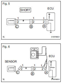
- If the wire harness is ground shorted (fig. 5), Locate the section by conducting a resistance check with the body ground (below).
- Check the resistance with the body ground.
- Disconnect connectors a and c, and measure the resistance
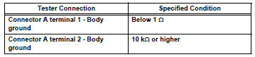
Standard resistance (fig. 6)
 Hint:
Hint:
Measure the resistance while lightly shaking the wire harness vertically and horizontally.
If the results match the examples above, a short circuit exists between terminal 1 of connector a and terminal 1 of connector c.
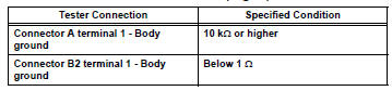
- Disconnect connector b and measure the resistance.
Standard resistance (fig. 7)
 If the results match the examples
above, a short
circuit exists between terminal 1 of connector b2
and terminal 1 of connector c.
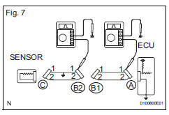
If the results match the examples above, a short circuit exists between terminal 1 of connector b2 and terminal 1 of connector c.
 Check for open circuit
For an open circuit in the wire harness in fig. 1,
Check the resistance or voltage, as described below.
Check the resistance.
Disconnect connectors a and c, and measure
the resi ...
 Check and replace ecu
Notice:
The connector should not be disconnected from
the ecu. Perform the inspection from the
backside of the connector on the wire harness
side.
When no measuring condition is specified, ...
Other materials:
4Wd control ecu communication stop mode
Description
Hint:
For vehicle with 4wd only.
Wiring diagram
Inspection procedure
Notice:
Turn the ignition switch off before measuring the resistances of the
main wire and the branch
wire.
After the ignition switch is turned off, check that the key reminder
warning system ...
Side doors
Unlocking and locking the doors
The vehicle can be locked and unlocked using the key, entry function,
wireless remote control or door lock switch.
Entry function (if equipped)
Wireless remote control
Key
Vehicles without a smart key system
Locks all the doors
Unlocks all the doors
Tur ...
Downhill assist control indicator light remains on
Description
When the downhill assist control switch is pushed on, the downhill assist
control function is available and
the downhill assist control indicator light illuminates.
Hint:
Even if the downhill assist control switch is pressed, the downhill assist
control indicator light will blink ...
