
Toyota RAV4 (XA40) 2013-2018 Service Manual: Check for open circuit
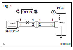
- For an open circuit in the wire harness in fig. 1, Check the resistance or voltage, as described below.
- Check the resistance.
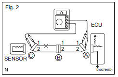
- Disconnect connectors a and c, and measure the resistance between them.
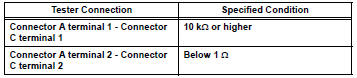
Standard resistance (fig. 2)
 Hint:
Hint:
Measure the resistance while lightly shaking the wire harness vertically and horizontally.
If the results match the examples above, an open circuit exists between terminal 1 of connector a and terminal 1 of connector c.
- Disconnect connector b and measure the resistance between the connectors.
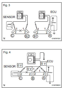
Standard resistance (fig. 3)
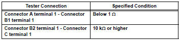 If the results match the examples
above, an
open circuit exists between terminal 1 of
connector b2 and terminal 1 of connector c.
- Check the voltage.
- In a circuit in which voltage is applied to the ecu
connector terminal, an open circuit can be
checked by conducting a voltage check.
With each connector still connected, measure the voltage between the body ground and these terminals (in this order): 1) terminal 1 of connector a, 2) terminal 1 of connector b, and 3) terminal 1 of connector c.
Standard voltage (fig. 4)
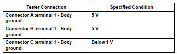 If the results match the examples
above, an
open circuit exists in the wire harness between
terminal 1 of connector b and terminal 1 of
connector c.
 Basic inspection
When measuring resistance of
electronic parts
Unless otherwise stated, all resistance
measurements should be made at an ambient
temperature of 20°c (68°f). Resistance
measurements m ...
 Check for short circuit
If the wire harness is ground shorted (fig. 5), Locate
the section by conducting a resistance check with
the body ground (below).
Check the resistance with the body ground.
Disconne ...
Other materials:
Front speed sensor
Components
Removal
Hint:
Use the same procedures for the lh side and rh side.
The procedures listed below are for the lh side.
Disconnect cable from negative battery
terminal
Caution:
Wait at least 90 seconds after disconnecting the
cable from the negative (-) battery termin ...
Air outlet damper control servo motor circuit
Description
The damper servo sends pulse signals to indicate the damper position to the
air conditioning amplifier.
The air conditioning amplifier activates the motor (normal or reverse) based on
these signals to move the
mode damper to the appropriate position, which controls the air o ...
Installation
Install rear no. 1 Seat assembly lh (w/o rear no. 2 Seat)
Fully tilt the seatback forward.
Place the seat in the cabin.
Notice:
Be careful not to damage the vehicle body.
Connection procedures of seat to lock cable when
reusing seat:
Using a screwdriver, detach the cla ...
