Toyota RAV4 (XA40) 2013-2018 Service Manual: Initialization
- Zero point calibration
Notice:
Make sure that the front passenger seat is not occupied before performing the operation.
Hint:
Perform the zero point calibration and sensitivity check if any of the following conditions apply.
- The occupant classification ecu is replaced.
- Accessories (seat cover etc.) Are installed.
- The front passenger seat is removed from the vehicle.
- The passenger airbag on/off indicator (off) comes on when the front passenger seat is not occupied.
- The vehicle is brought to the workshop for repair due to an accident or a collision.
- Zero point calibration and sensitivity check procedures:
Hint:
Make sure that the zero point calibration has finished normally, and then perform the sensitivity check.
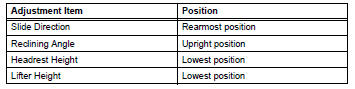
- Adjust the seat position in accordance with the
table below.
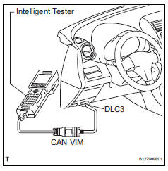
- Connect the intelligent tester (with can vim) to the dlc3.
- Turn the ignition switch on.
- Perform the zero point calibration by following the prompts on the tester screen.
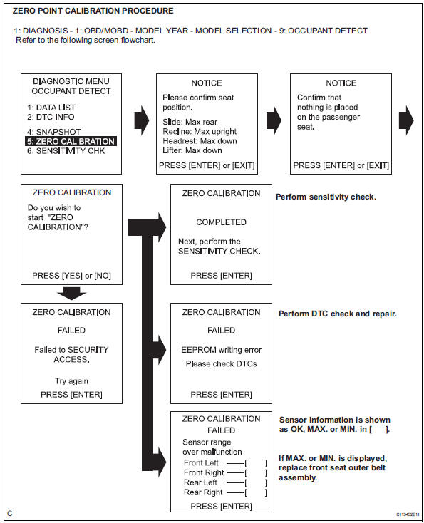
Hint:
Refer to the intelligent tester operator's manual for further details.
Ok: completed is displayed.
- Perform the sensitivity check by following the prompts on the tester screen.
- Confirm that the beginning sensor reading is within the standard range.
Standard range: -3.2 To 3.2 Kg (-7 to 7 lb)
- Place a 30 kg (66.14 Lb) weight (e.G. A lead mass) onto the front passenger seat.
- Confirm that the sensitivity is within the standard range.
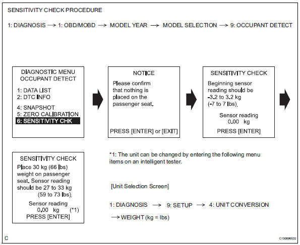
Standard range: 27 to 33 kg (59.52 To 72.75 Lb)
Hint:
- When performing the sensitivity check, use a solid metal weight (the check result may not be accurate if a liquid weight is used).
- If the sensitivity deviates from the standard range, retighten the bolts of the front passenger seat taking care not to deform the seat rail. After performing this procedure, if the sensitivity is not within the standard range, replace the front seat assembly rh.
- If the zero point calibration has not finished normally, replace the front seat assembly rh.
 How to proceed with troubleshooting
Hint:
Use the following procedures to troubleshoot the occupant
classification system.
*: Use the intelligent tester.
Vehicle brought to workshop
Passenger airbag on/off indicato ...
 Problem symptoms table
Hint:
Use the table below to help determine the cause of the
problem symptom. The potential causes of the symptoms
are listed in order of probability in the "suspected area"
column ...
Other materials:
On-vehicle inspection
Check battery condition
Notice:
If the battery is weak or if the engine is difficult to
start, perform the following procedures.
Check the battery for damage and deformation. If
severe damage, deformation or leakage is found,
replace the battery.
Check the electrolyte quantity of e ...
Electronic control
Removal and installation of battery
terminal
Notice:
Certain systems need to be initialized after
disconnecting and reconnecting the cable from
the negative (-) battery terminal.
Before performing electronic work, disconnect
the cable from the negative (-) battery terminal to
...
Turn signal light circuit
Description
The turn signal flasher relay (marking: flsh) in the main body ecu turns on
when it receives signals
from the headlight dimmer switch integrated with the turn signal switch, causing
the turn signal lights to
flash.
Wiring diagram
Inspection procedure
Check operation of t ...
