Toyota RAV4 (XA40) 2013-2018 Service Manual: Tc and cg terminal circuit
Description
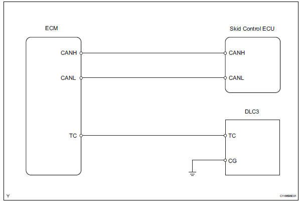
Connecting terminals tc and cg of the dlc3 causes the skid control ecu to display 2-digit dtcs by flashing the abs warning light.
Wiring diagram
Inspection procedure
- Check dlc3 (tc voltage)
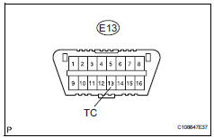
- Turn the ignition switch on.
- Measure the voltage of the dlc3.
Standard voltage 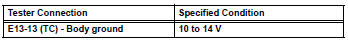


- Check can communication system
- Check the dtc (see page ca-34).
Result 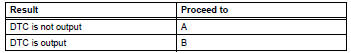

Replace abs and traction actuator assembly
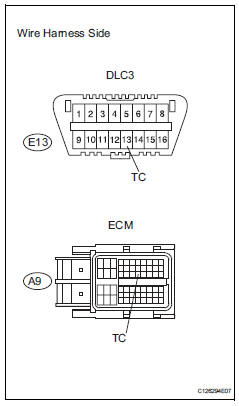
- Check wire harness (dlc3 - ecm and body ground)
- Turn the ignition switch off.
- Disconnect the a12 ecm connector.
- Measure the resistance of the wire harness side connectors.
Standard resistance 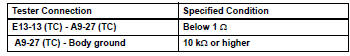

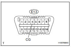
- Check wire harness (dlc3 - body ground)
- Measure the resistance of the dlc3.
Standard resistance 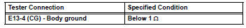

- Check can communication system
- Check if the can communication dtc is output (see page ca-34).
Result 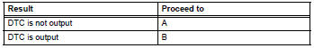

Replace abs and traction actuator assembly
 Skid control buzzer circuit
Description
The skid control buzzer sounds while the vsc is activated.
Wiring diagram
Inspection procedure
Notice:
When replacing the abs and traction actuator, perform the zero point
calib ...
 Ts and cg terminal circuit
Description
If the vehicle is stationary during sensor check mode, speed sensor
malfunctions cannot be detected. The
vehicle must be driven for speed sensor malfunctions to be detected.
Hint:
...
Other materials:
Throttle / pedal position sensor / switch "A"
Hint:
These dtcs relate to the throttle position (tp) sensor.
Description
The tp sensor is mounted on the throttle body, and detects the opening angle
of the throttle valve. This
sensor is a non-contact type. It uses hall-effect elements in order to yield
accurate signals even in
extrem ...
Playing back mp3 and wma discs
Power
Volume
Cd eject
Selecting a file or displaying
folder list
Searching playback
Next commands, random play
or back button
Repeat play
Fast-forwarding, rewinding or
selecting a folder
Changing the audio source/
playback
Playback/pause
Previous commands
Selecti ...
Front speed sensor
Components
Removal
Hint:
Use the same procedures for the lh side and rh side.
The procedures listed below are for the lh side.
Disconnect cable from negative battery
terminal
Caution:
Wait at least 90 seconds after disconnecting the
cable from the negative (-) battery termin ...
