Toyota RAV4 (XA40) 2013-2018 Service Manual: Skid control buzzer circuit
Description
The skid control buzzer sounds while the vsc is activated.
Wiring diagram
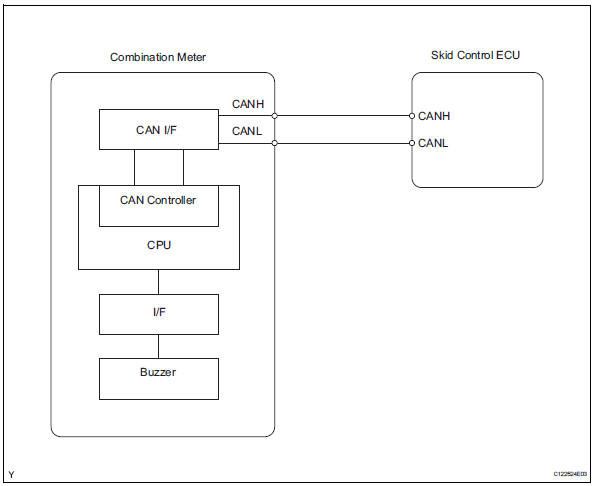
Inspection procedure
Notice:
When replacing the abs and traction actuator, perform the zero point calibration (see page bc- 24).
- Check can communication system
- Check if the can communication dtc is output (see page ca-34).
Result 

- Perform active test by intelligent tester (skid control buzzer)
- Select the active test, generate a control command, and then check that the skid control buzzer operate.

Ok: the skid control buzzer can be heard.

- Inspect combination meter
- Inspect the combination meter (see page me-15).


Replace abs and traction actuator assembly
 Auto lsd indicator light does not come on
Description
Refer to the description of "auto lsd indicator light remains on" (see page
bc-164).
Wiring diagram
Refer to the auto lsd indicator light circuit (see page bc-165).
Inspect ...
 Tc and cg terminal circuit
Description
Connecting terminals tc and cg of the dlc3 causes the skid control ecu to
display 2-digit dtcs by
flashing the abs warning light.
Wiring diagram
Inspection procedure
Check dl ...
Other materials:
Thermostat
Components
Removal
Remove no. 1 Engine under cover
Drain engine coolant (see page co-6)
Remove radiator support opening cover
Disconnect no. 2 Radiator hose
Remove water inlet
Remove the 2 nuts and disconnect the water inlet
from the cylinder block.
Remove thermostat
...
Indications on multi-information
display
Vehicles with 7-inch display
LTA indicator
The illumination condition of the
indicator informs the driver of the
system operation status.
Illuminated in white: LTA system is
operating.
Illuminated in green: Steering
wheel assistance of the steering
assist function or lane centering
function is ...
Short in front driver side - side squib circuit
Description
The driver side - side squib circuit consists of the center airbag sensor and
the front seat side airbag lh.
This circuit instructs the srs to deploy when the deployment conditions are met.
These dtcs are recorded when a malfunction is detected in the driver side - side
sq ...
