Toyota RAV4 (XA40) 2013-2018 Service Manual: Evaporative emission system reference orifice
Dtc summary
Hint:
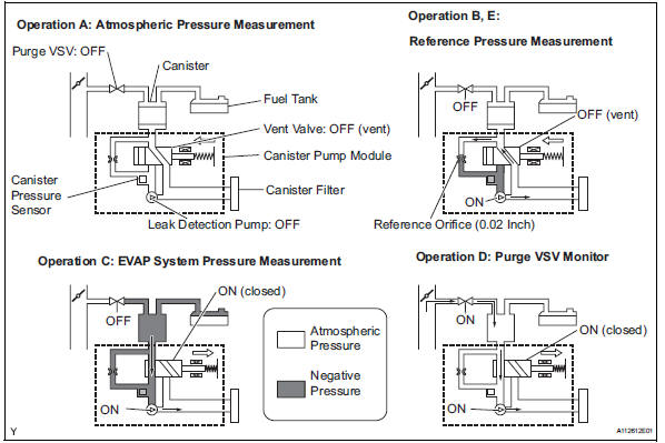
The reference orifice is located inside the canister pump module.
Description
The description can be found in the evap (evaporative emission) system (see page es-335).
Inspection procedure
Refer to the evap system (see page es-340).
Monitor description
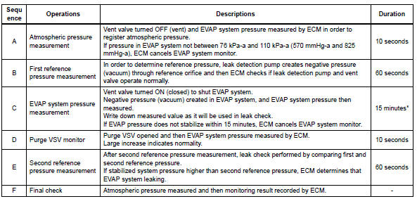
5 Hours* after the ignition switch is turned off, the leak detection pump creates negative pressure (vacuum) in the evap system. The ecm monitors for leaks and actuator malfunctions based on the evap pressure.
Hint:
*: If the engine coolant temperature is not below 35°c (95°f) 5 hours after the ignition switch is turned off, the monitor check starts 2 hours later. If it is still not below 35°c (95°f) 7 hours after the ignition switch is turned off, the monitor check starts 2.5 Hours later.

*: If only a small amount of fuel is in the fuel tank, it takes longer for the evap pressure to stabilize.
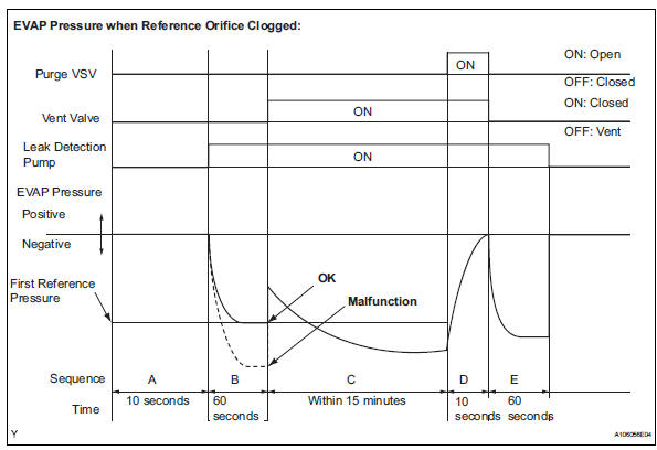
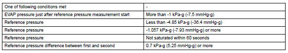
- P043e: reference orifice clogged
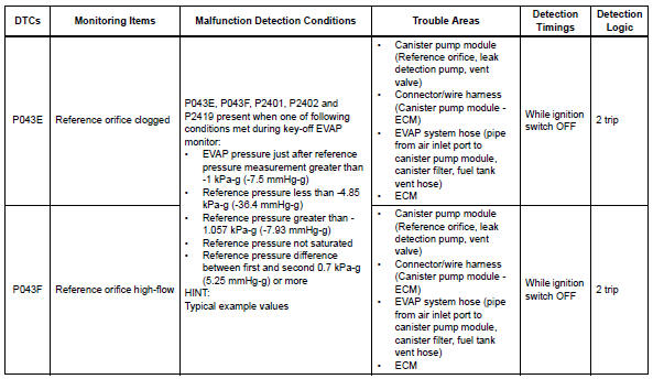
In operation b, the leak detection pump creates negative pressure (vacuum) through the reference orifice.
The evap system pressure is then measured by the ecm, using the canister pressure sensor, to determine the reference pressure. If the pressure is lower than -4.85 Kpa-g (-36.4 Mmhg-g), the ecm interprets this as a clog malfunction in the reference orifice, and stops the evap system monitor.
The ecm then illuminates the mil and sets the dtc (2 trip detection logic).
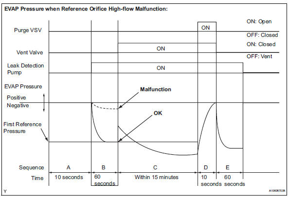
- P043f: reference orifice high-flow
In operation b, the leak detection pump creates negative pressure (vacuum) through the reference orifice.
The evap system pressure is then measured by the ecm using the canister pressure sensor to determine the reference pressure. If the pressure is higher than -1.057 Kpa-g (-7.93 Mmhg-g), the ecm interprets this as a high-flow malfunction in the reference orifice, and stops the evap system monitor. The ecm then illuminates the mil and sets the dtc (2 trip detection logic).
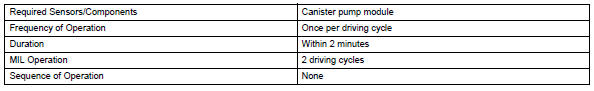
Monitor strategy
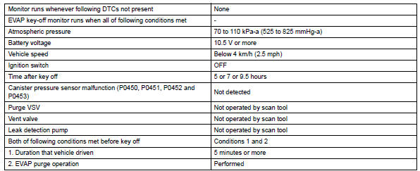
Typical enabling conditions
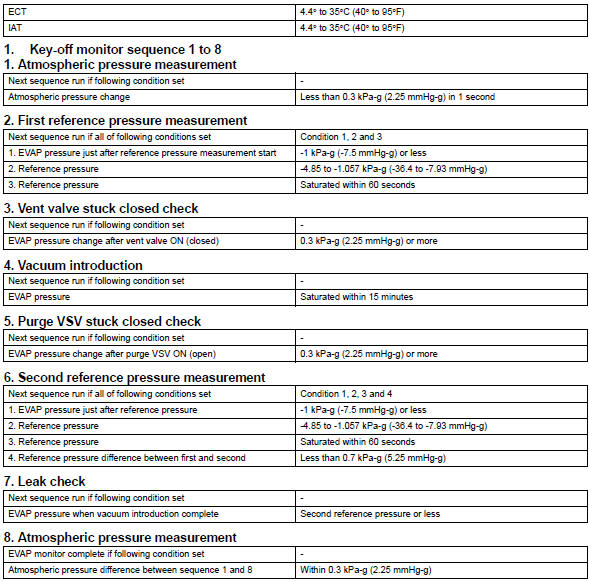
Typical malfunction thresholds
"Saturated" indicates that the evap pressure change is less than 0.286 Kpa-g (2.14 Mmhg-g) in 60 seconds.
Monitor result
Refer to checking monitor status (see page es-17).
 Catalyst system efficiency below threshold (bank 1)
Monitor description
The ecm uses sensors mounted in front of and behind the three-way catalytic
converter (twc) to
monitor its efficiency.
The first sensor, the air-fuel ratio (a/f) sensor, ...
 Evaporative emission control system incorrect purge flow
Dtc summary
Description
The description can be found in the evap (evaporative emission) system (see
page es-335).
Inspection procedure
Refer to the evap system (see page es-340).
Monito ...
Other materials:
Removal and installation of fuel control
parts
Place for removing and installing fuel
system parts
Work in a location with good air ventilation that
does not have welders, grinders, drills, electric
motors, stoves, or any other ignition sources.
Never work in a pit or near a pit as vaporized
fuel will collect in those places.
...
Data list / active test
Read data list
Hint:
Using the intelligent tester's data list allows switch,
actuator and other item values to be read without
removing any parts. Reading the data list early in
troubleshooting is one way to save time.
Connect the intelligent tester (with can vim) to the
dlc3.
Turn ...
Removal (2005/11-2006/01)
Remove front wheel
Drain automatic transaxle fluid
Drain the automatic transaxle fluid for u140f (see
page ax-147).
Drain the automatic transaxle fluid for u241e (see
page ax-146).
Remove front axle hub nut (see page ah-6)
Disconnect front speed sensor lh
Disconnect th ...
