
Toyota RAV4 (XA40) 2013-2018 Service Manual: Diagnostic trouble code chart
Hint:
Parameters listed in the chart may be different than your readings depending on the type of instrument and other factors.
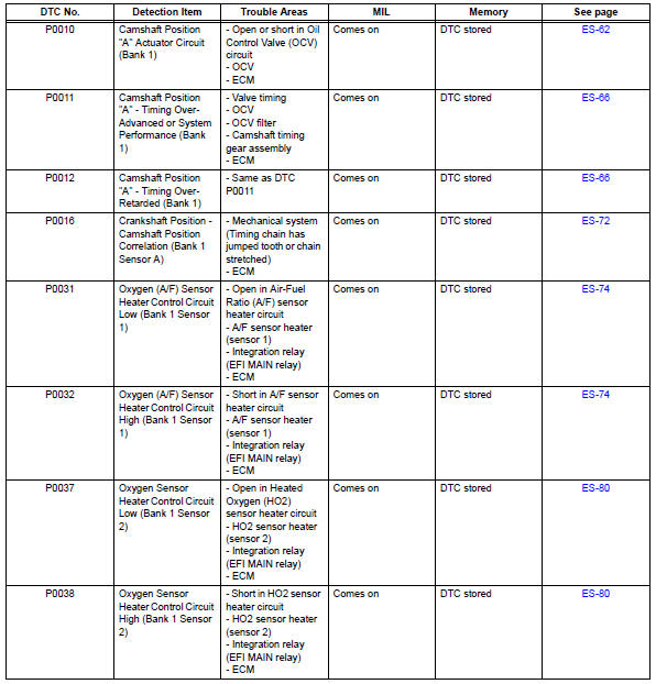
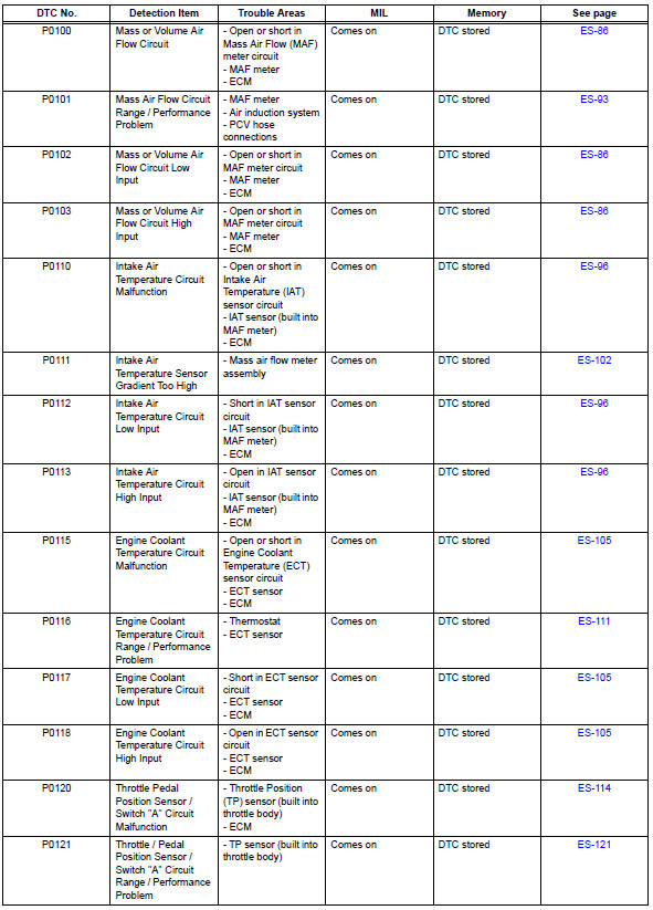
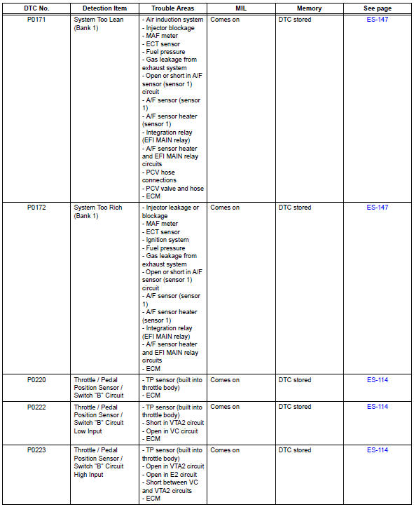
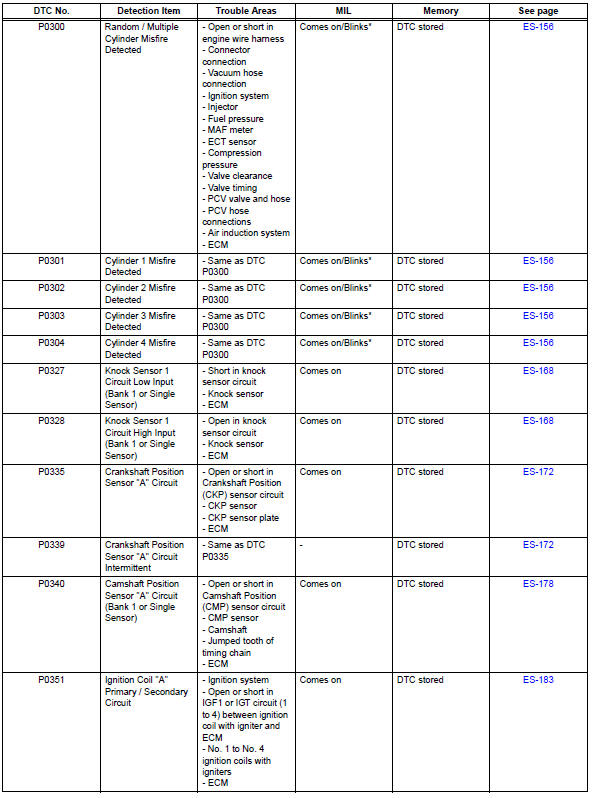
If any dtcs are displayed during a check mode dtc check, check the circuit for the dtcs listed in the table below. For details of each dtc, refer to the page indicated.

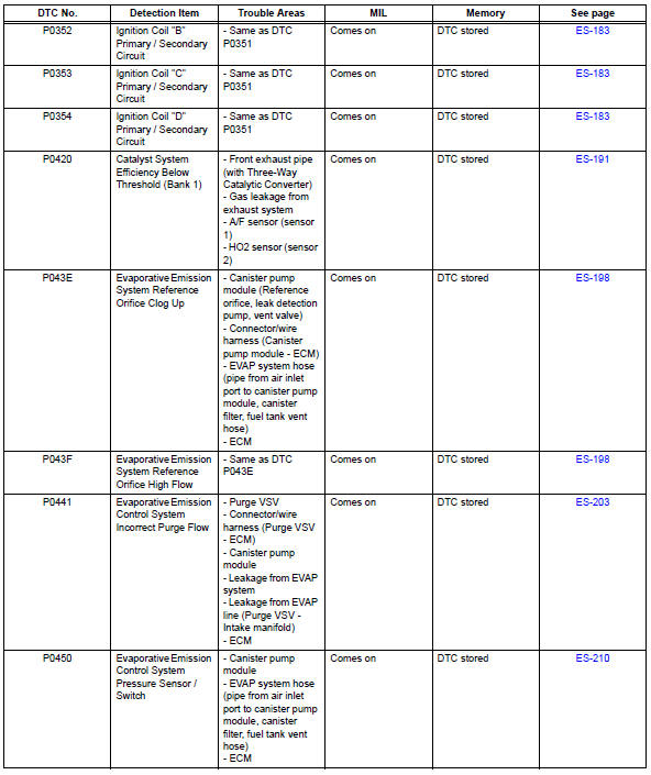
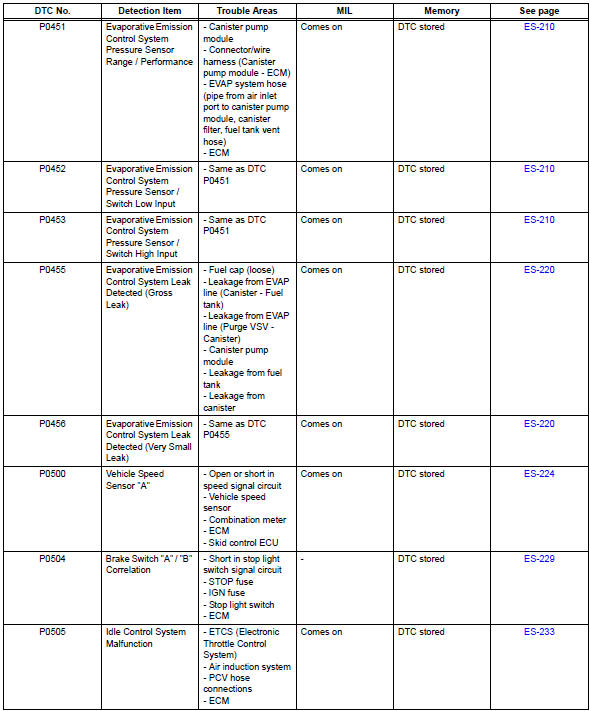
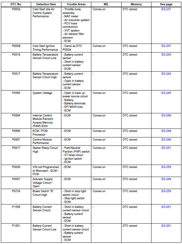
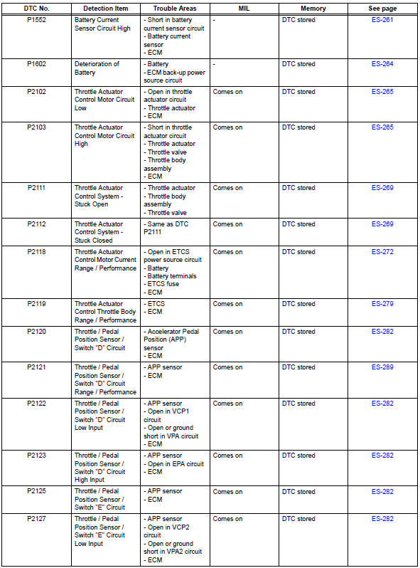
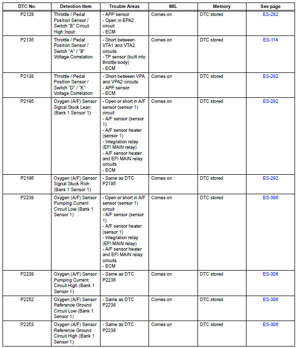
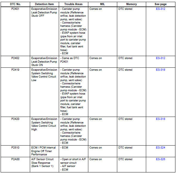
Hint:
*: Mil flashes when a catalyst damaged misfire is detected.
- Camshaft position "a" actuator circuit (bank 1)
- Camshaft position "A"
- Camshaft position correlation (bank 1 sensor a)
- Oxygen (a/f) sensor heater control circuit
- Mass or volume air flow circuit
- Mass air flow circuit range / performance problem
- Intake air temperature circuit malfunction
- Intake air temperature sensor gradient too high
- Engine coolant temperature circuit
- Engine coolant temperature circuit range / performance problem
- Throttle / pedal position sensor / switch "A"
- Throttle / pedal position sensor / switch "A" circuit range / performance problem
- Insufficient coolant temperature for closed loop fuel control
- Coolant thermostat (coolant temperature below thermostat regulating temperature)
- Oxygen sensor circuit
- System too
- Random / multiple cylinder misfire detected
- Knock sensor 1 circuit
- Crankshaft position sensor "A"
- Camshaft position sensor "a" circuit (bank 1 or single sensor)
- Ignition coil
- Catalyst system efficiency below threshold (bank 1)
- Evaporative emission system reference orifice
- Evaporative emission control system incorrect purge flow
- Evaporative emission control system pressure sensor
- Evaporative emission control system leak detected
- Vehicle speed sensor "A"
- Brake switch "A" / "B" correlation
- Idle control system malfunction
- Cold start
- Battery temperature sensor circuit
- System voltage
- Internal control module random access memory (ram) error
- Starter relay circuit high
- Vin not programmed or mismatch - ecm / pcm
- Brake switch "b" circuit high
- Battery current sensor circuit
- Deterioration of battery
- Throttle actuator control motor circuit
- Throttle actuator control system
- Throttle actuator control motor current range / performance
- Throttle actuator control throttle body range / performance
- Throttle / pedal position sensor
- Throttle / pedal position sensor / switch "d" circuit range / performance
- Oxygen (a/f) sensor signal stuck
- Oxygen (a/f) sensor pumping current circuit
- Evaporative emission leak detection pump
- Evaporative emission system switching valve control
- Ecm / pcm internal engine off timer performance
- A/f sensor circuit slow response (bank 1 sensor 1)
- Evap system
- Ecm power source circuit
- Vc output circuit
- Fuel pump control circuit
- Mil circuit
 System check
Hint:
Performing a system check enables the system,
which consists of multiple actuators, to be operated
without removing any parts. In addition, it can show
whether or not any dtcs are set, and c ...
 Camshaft position "a" actuator circuit (bank 1)
Dtc P0010 Camshaft
position "a" actuator circuit (bank
1)
Description
The variable valve timing (vvt) system includes the ecm, ocv and vvt
controller. The ecm sends a
target du ...
Other materials:
Outside rear view mirrors
The rear view mirror's position
can be adjusted to
enable sufficient confirmation
of the rear view.
â– When using the outside rear
view mirrors in a cold weather
When it is cold and the outside rear
view mirrors are frozen, it may not
be possible to fold/extend them or
adjust the mirror surface. Rem ...
Brake pedal load sensing switch
On-vehicle inspection
Inspect brake pedal load sensing switch
Hint:
Do not remove the brake pedal load sensing switch
from the brake pedal support.
When there is a malfunction in the brake pedal load
sensing switch, replace the brake pedal support.
Disconnect the brake pedal l ...
Repair
Repair valve seats
If the seating is too high on the valve face, use 30°
and 45° cutters to correct the seat.
If the seating is too low on the valve face, use 75°
and 45° cutters to correct the seat.
Standard width
Lap the valve and valve seat by hand with an
abrasiv ...
