Toyota RAV4 (XA40) 2013-2018 Service Manual: Throttle actuator control throttle body range / performance

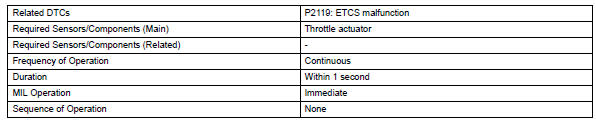
Description
The electronic throttle control system (etcs) is composed of the throttle actuator, throttle position (tp) sensor, accelerator pedal position (app) sensor, and ecm. The ecm operates the throttle actuator to regulate the throttle valve in response to driver inputs. The tp sensor detects the opening angle of the throttle valve, and provides the ecm with feedback so that the throttle valve can be appropriately controlled by the ecm.
![]()
Monitor description
The ecm determines the actual opening angle of the throttle valve from the tp sensor signal. The actual opening angle is compared to the target opening angle commanded by the ecm. If the difference between these two values is outside the standard range, the ecm interprets this as a malfunction in the etcs. The ecm then illuminates the mil and sets the dtc.
If the malfunction is not repaired successfully, the dtc is set when the accelerator pedal is quickly released (to close the throttle valve) after the engine speed reaches 5,000 rpm by the accelerator pedal being fully depressed (fully open the throttle valve).
Monitor strategy
Typical enabling conditions
![]()
Typical malfunction thresholds

Fail-safe
When this dtc, or other dtcs relating to etcs (electronic throttle control system) malfunctions, are set, the ecm enters fail-safe mode. During fail-safe mode, the ecm cuts the current to the throttle actuator off, and the throttle valve is returned to a 6° throttle angle by the return spring. The ecm then adjusts the engine output by controlling the fuel injection (intermittent fuel-cut) and ignition timing, in accordance with the accelerator pedal opening angle, to allow the vehicle to continue at a minimal speed.
If the accelerator pedal is depressed firmly and gently, the vehicle can be driven slowly.
Fail-safe mode continues until a pass condition is detected, and the ignition switch is then turned to off.
Wiring diagram
Refer to dtc p2102 (see page es-266).
Inspection procedure
Hint:
Read freeze frame data using the intelligent tester. Freeze frame data records the engine condition when malfunctions are detected. When troubleshooting, freeze frame data can help determine if the vehicle was moving or stationary, if the engine was warmed up or not, if the air-fuel ratio was lean or rich, and other data from the time the malfunction occurred.
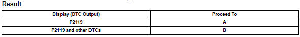
- Check any other dtcs output (in addition to dtc p2119)
- Connect the intelligent tester to the dlc3.
- Turn the ignition switch on.
- Turn the tester on.
- Select the following menu items: diagnosis / enhanced obd ii / dtc info / current codes.
- Read dtcs.
Hint:
If any dtcs other than p2119 are output, troubleshoot those dtcs first.


- Check whether dtc output recurs (dtc p2119)
- Connect the intelligent tester to the dlc3.
- Turn the ignition switch on.
- Turn the tester on.
- Clear dtcs (see page es-35).
- Allow the engine to idle for 15 seconds.
Caution:
Exercise extreme care and take precautions in steps (f) and (g) below. Failure to do so may result in the vehicle unexpectedly rolling away.
- Securely apply the parking brake and move the gear selector lever to the d position.
- While depressing the brake pedal securely, fully depress the accelerator pedal for 5 seconds.
- On the tester, select the following menu items:
Diagnosis / enhanced obd ii / dtc info / current codes.
- Read dtcs.
Hint:
The output voltage of the throttle position sensor can be checked during step (g) using the intelligent tester. Variations in the output voltage indicate that the throttle actuator is in operation. To check the output voltage using the intelligent tester, select the following menu items: diagnosis / enhanced obd ii / data list / etcs / throttle pos #1.
Ok: no dtc output.

 Throttle actuator control motor current range / performance
Description
The etcs (electronic throttle control system) has a dedicated power supply
circuit. The voltage (+bm)
is monitored and when it is low (less than 4 v), the ecm determines that there ...
 Throttle / pedal position sensor
Hint:
These dtcs relate to the accelerator pedal position (app) sensor.
Description
Hint:
This etcs (electronic throttle control system) does not use a throttle cable.
The app sensor is mou ...
Other materials:
Inspection
Inspect cylinder head for warpage
Using a precision straightedge and feeler gauge,
measure the warpage of the contact surfaces of the
cylinder block and manifolds.
Maximum warpage:
0.08 Mm (0.0032 In.)
If the warpage is greater than the maximum, replace
the cylinder head sub-a ...
Dtc check / clear
Check dtc (when using intelligent tester)
Connect the intelligent tester (with can vim) to the
dlc3.
Turn the ignition switch on.
Turn the tester on.
Read the dtcs by following the prompts on the
tester screen.
Hint:
Refer to the intelligent tester operator's manual for
furth ...
Ecm power source circuit
Description
When the ignition switch is turned on, the battery voltage is applied to the
igsw of the ecm. The output
signal from the mrel terminal of the ecm causes a current to flow to the coil,
closing the contacts of the
integration relay (efi main relay) and supplying power to either term ...
